User Manual (ENGLISH)
Page 2
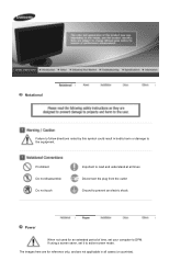
The images here are not applicable in bodily harm or damage to the equipment. Notational Failure to follow directions noted by this symbol could result in all times Disconnect the plug from the outlet Ground to prevent an electric shock Power When not used for reference only, and are for an extended period of time, set it to DPM. Prohibited Do not disassemble Do not touch Important to read and understand at all cases (or countries). If using a screen saver, set your computer to active screen mode.
The images here are not applicable in bodily harm or damage to the equipment. Notational Failure to follow directions noted by this symbol could result in all times Disconnect the plug from the outlet Ground to prevent an electric shock Power When not used for reference only, and are for an extended period of time, set it to DPM. Prohibited Do not disassemble Do not touch Important to read and understand at all cases (or countries). If using a screen saver, set your computer to active screen mode.
Service Manual
Page 3
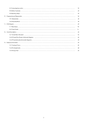
Reference Information ...46 13-1 Technical Terms ...46 13-2 Pin Assignments ...48 13-3 Timing Chart ...49 3 Circuit Descriptions ...42 12-1 Overall Block Structture ...42 12-2 IP Board Part (Power) Schematic Diagrams ...44 12-3 IP Board (Inverter) Schematic Diagrams ...45 13. Disassembly and Reassembly ...36 10-1 Disassembly ...36 10-2 Assembly Block ...39 11. PCB Diagram ...40 11-1 Mian Board...40 12-2 Power Board...41 12. 9-3 Connecting the monitor ...33 9-4 Monitor Assembly ... 34 9-5 Attaching a Base ... 35 10.
Reference Information ...46 13-1 Technical Terms ...46 13-2 Pin Assignments ...48 13-3 Timing Chart ...49 3 Circuit Descriptions ...42 12-1 Overall Block Structture ...42 12-2 IP Board Part (Power) Schematic Diagrams ...44 12-3 IP Board (Inverter) Schematic Diagrams ...45 13. Disassembly and Reassembly ...36 10-1 Disassembly ...36 10-2 Assembly Block ...39 11. PCB Diagram ...40 11-1 Mian Board...40 12-2 Power Board...41 12. 9-3 Connecting the monitor ...33 9-4 Monitor Assembly ... 34 9-5 Attaching a Base ... 35 10.
Service Manual
Page 35
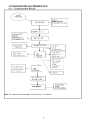
10 Disassembly and Reassembly 10-1 Disassembly Block LE 2294 LCD Monitor ASSY BASE*1 BASE*1 RUBBER FOOT*4 SCREW,MINUS,M4*8,Zn* 1 STAND_BACK*1 HINGE *1 SCREW M4*10 *3 STAND_FRONT*1 SCREW M4*10, *3 ASSY STAND*1 BACK COVER*1 BKT-VESA *4 SHIELDING*1 TAPE,ACE,(PC=10x4 LCP 22 MT220WW01-V0G1 (INNOLUX)& LCP 22 N220Z1-L01(A)(CMO)& LCP 22 MT220WW01-V2- ASSY BACK COVER*1 ASSY...
10 Disassembly and Reassembly 10-1 Disassembly Block LE 2294 LCD Monitor ASSY BASE*1 BASE*1 RUBBER FOOT*4 SCREW,MINUS,M4*8,Zn* 1 STAND_BACK*1 HINGE *1 SCREW M4*10 *3 STAND_FRONT*1 SCREW M4*10, *3 ASSY STAND*1 BACK COVER*1 BKT-VESA *4 SHIELDING*1 TAPE,ACE,(PC=10x4 LCP 22 MT220WW01-V0G1 (INNOLUX)& LCP 22 N220Z1-L01(A)(CMO)& LCP 22 MT220WW01-V2- ASSY BACK COVER*1 ASSY...

