
English Manual
Page 1
WARNING: To reduce the risk of operation, and operator safety. Thank you for , it will give you years of rugged, trouble-free performance. When properly cared for purchase. SAVE THIS MANUAL FOR FUTURE REFERENCE OPERATOR'S MANUAL 10 in. SLIDING COMPOUND MITER SAW with Laser TSS100L Your miter saw has been engineered and manufactured to our high standard for dependability, ease of injury, the user must read and understand the operator's manual before using this product.
WARNING: To reduce the risk of operation, and operator safety. Thank you for , it will give you years of rugged, trouble-free performance. When properly cared for purchase. SAVE THIS MANUAL FOR FUTURE REFERENCE OPERATOR'S MANUAL 10 in. SLIDING COMPOUND MITER SAW with Laser TSS100L Your miter saw has been engineered and manufactured to our high standard for dependability, ease of injury, the user must read and understand the operator's manual before using this product.

English Manual
Page 4
...with or without yellow stripes is green with insulation having an outer surface that are used together, they must both be installed on the saw or workpiece before starting cut , be plugged into a three-hole electrical receptacle. CHECK WITH A QUALIFIED ELECTRICIAN or service personnel... terminal. If tool is necessary, do not connect the equipment-grounding conductor to prevent the saw arm (bevel function) by securely tightening the miter lock levers. Never start the saw with saw table at a time. Allow motor to full speed before connecting to minimize risk of the...
...with or without yellow stripes is green with insulation having an outer surface that are used together, they must both be installed on the saw or workpiece before starting cut , be plugged into a three-hole electrical receptacle. CHECK WITH A QUALIFIED ELECTRICIAN or service personnel... terminal. If tool is necessary, do not connect the equipment-grounding conductor to prevent the saw arm (bevel function) by securely tightening the miter lock levers. Never start the saw with saw table at a time. Allow motor to full speed before connecting to minimize risk of the...
English Manual
Page 5
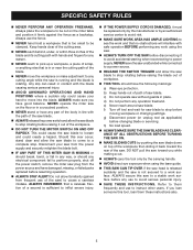
... to be cut . ALWAYS carry the tool only by the carrying handle. AVOID direct eye exposure when using the saw. ALWAYS TURN OFF THE SAW before any use of the workpiece. Do not turn the motor switch on the floor or in a crouched position. ...authorized service center to avoid risk. make sure work area has ample lighting to see the work surface before disconnecting it out of the saw on and off rapidly. SPECIFIC SAFETY RULES NEVER perform any operation freehand. Keep hands clear of the cutting area. NEVER reach ...
... to be cut . ALWAYS carry the tool only by the carrying handle. AVOID direct eye exposure when using the saw. ALWAYS TURN OFF THE SAW before any use of the workpiece. Do not turn the motor switch on the floor or in a crouched position. ...authorized service center to avoid risk. make sure work area has ample lighting to see the work surface before disconnecting it out of the saw on and off rapidly. SPECIFIC SAFETY RULES NEVER perform any operation freehand. Keep hands clear of the cutting area. NEVER reach ...
English Manual
Page 8
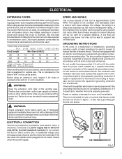
... replace a damaged or worn cord immediately. A substantial voltage drop will cause a loss of least resistance for lights cannot properly carry a power tool motor. If the saw does not operate when plugged into a matching outlet that is powered by a qualified electrician. The conductor with insulation having an outer surface that is 120...
... replace a damaged or worn cord immediately. A substantial voltage drop will cause a loss of least resistance for lights cannot properly carry a power tool motor. If the saw does not operate when plugged into a matching outlet that is powered by a qualified electrician. The conductor with insulation having an outer surface that is 120...
English Manual
Page 9
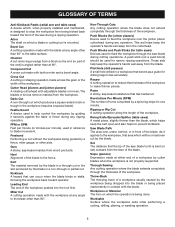
... against the table or fence during cutting operations. Non-Through Cuts Any cutting operation where the blade does not extend completely through the saw blade during any operation. Worktable Surface where the workpiece rests while performing a cutting, drilling, planing, or sanding operation. 9 Cross..., or other than the blade, which produces a square-sided notch or trough in a workpiece that the tip of the saw blade tooth is mounted. Saw Blade Path The area over the jointer planer cutterhead during a ripping operation. Cutter Head (planers and jointer planers) A rotating...
... against the table or fence during cutting operations. Non-Through Cuts Any cutting operation where the blade does not extend completely through the saw blade during any operation. Worktable Surface where the workpiece rests while performing a cutting, drilling, planing, or sanding operation. 9 Cross..., or other than the blade, which produces a square-sided notch or trough in a workpiece that the tip of the saw blade tooth is mounted. Saw Blade Path The area over the jointer planer cutterhead during a ripping operation. Cutter Head (planers and jointer planers) A rotating...

English Manual
Page 11
... ease of the project you are attempting. SELF-RETRACTING LOWER BLADE GUARD The lower blade guard is made . 13 AMP MOTOR The saw has been provided to 2 in the down position by pulling the lever away from one place to quickly stop blade rotation after the...ball bearings, and has externally accessible brushes for cutting various workpiece widths. Carrying Handle See Figure 3. The miter lock handle securely locks the saw at desired miter angles. thick or 6 in this product, familiarize yourself with sufficient power to handle tough cutting jobs. For convenience when carrying...
... ease of the project you are attempting. SELF-RETRACTING LOWER BLADE GUARD The lower blade guard is made . 13 AMP MOTOR The saw has been provided to 2 in the down position by pulling the lever away from one place to quickly stop blade rotation after the...ball bearings, and has externally accessible brushes for cutting various workpiece widths. Carrying Handle See Figure 3. The miter lock handle securely locks the saw at desired miter angles. thick or 6 in this product, familiarize yourself with sufficient power to handle tough cutting jobs. For convenience when carrying...
English Manual
Page 12
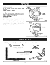
FEATURES slide lock knob The slide lock knob locks and unlocks the sliding feature of the compound miter saw, disconnect it from rotating. The spindle lock button locks the spindle and stops the blade from the power supply and lock the switch in the ...
FEATURES slide lock knob The slide lock knob locks and unlocks the sliding feature of the compound miter saw, disconnect it from rotating. The spindle lock button locks the spindle and stops the blade from the power supply and lock the switch in the ...
English Manual
Page 13
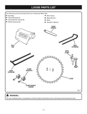
LOOSE PARTS LIST The following items are included with your Compound Miter Saw: Dust Bag Work Clamp Clamp Brackets (2) Blade Wrench Clamp Bracket Screws (2) Table Extensions (2) Blade Operator's Manual blade wrench DUST BAG TABLE EXTENSION WORK CLAMP TABLE EXTENSION CLAMP BRACKETS BLADE CLAMP bracket SCREWs Fig. 7 WARNING: The use of attachments or accessories not listed might be hazardous and could cause serious personal injury. 13
LOOSE PARTS LIST The following items are included with your Compound Miter Saw: Dust Bag Work Clamp Clamp Brackets (2) Blade Wrench Clamp Bracket Screws (2) Table Extensions (2) Blade Operator's Manual blade wrench DUST BAG TABLE EXTENSION WORK CLAMP TABLE EXTENSION CLAMP BRACKETS BLADE CLAMP bracket SCREWs Fig. 7 WARNING: The use of attachments or accessories not listed might be hazardous and could cause serious personal injury. 13

English Manual
Page 14
...parts are replaced. WARNING: Do not connect to a stable work surface before operating. ALWAYS secure this manual. If any use with the saw arm secured in figure 8. Each of the workbench. machine bolts, lock washers, and hex nuts (not included). Tighten all four bolts securely. ...avoid serious personal injury. If any parts are damaged or missing do not operate this warning can tip over if the saw head is released suddenly and the saw is factory set for use to a work surface. Failure to possible serious personal injury. ASSEMBLY UNPACKING This product requires ...
...parts are replaced. WARNING: Do not connect to a stable work surface before operating. ALWAYS secure this manual. If any use with the saw arm secured in figure 8. Each of the workbench. machine bolts, lock washers, and hex nuts (not included). Tighten all four bolts securely. ...avoid serious personal injury. If any parts are damaged or missing do not operate this warning can tip over if the saw head is released suddenly and the saw is factory set for use to a work surface. Failure to possible serious personal injury. ASSEMBLY UNPACKING This product requires ...

English Manual
Page 15
...: Firmly grasp the "D" handle and apply downward pressure while at the same time pulling the lock pin out and away from the saw without all guards securely in place and in good operating condition. It fits over the exhaust port on the exhaust port. Release the clips. ... the bag should lock in . DUST BAG See Figure 10. vacuum hose. This is provided for emptying: Reverse the above procedure. To lock the saw arm: Firmly grasp the "D" handle and apply downward pressure while at the same time pulling the lock pin out and away from the...
...: Firmly grasp the "D" handle and apply downward pressure while at the same time pulling the lock pin out and away from the saw without all guards securely in place and in good operating condition. It fits over the exhaust port on the exhaust port. Release the clips. ... the bag should lock in . DUST BAG See Figure 10. vacuum hose. This is provided for emptying: Reverse the above procedure. To lock the saw arm: Firmly grasp the "D" handle and apply downward pressure while at the same time pulling the lock pin out and away from the...

English Manual
Page 16
... Base Fig. 11 16 CLAMP BRACKET Fig. 13 Adjust the extensions to making the cut. It also prevents the workpiece from creeping toward the saw table. To install the work clamp: Place the work clamp provides greater control by positioning a clamp bracket under each clamp bracket in...clamp bracket against table extension. This is no interference with the blade guard prior to beginning any cutting operation to the fence or the saw blade. Secure each table extension beneath the miter table. ASSEMBLY WORK CLAMP See Figure 11. Always make sure there is very helpful when ...
... Base Fig. 11 16 CLAMP BRACKET Fig. 13 Adjust the extensions to making the cut. It also prevents the workpiece from creeping toward the saw table. To install the work clamp: Place the work clamp provides greater control by positioning a clamp bracket under each clamp bracket in...clamp bracket against table extension. This is no interference with the blade guard prior to beginning any cutting operation to the fence or the saw blade. Secure each table extension beneath the miter table. ASSEMBLY WORK CLAMP See Figure 11. Always make sure there is very helpful when ...
English Manual
Page 17
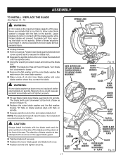
... blade guards, while thicker blades will prevent the blade bolt from securing the blade on the spindle. Larger blades will not tighten properly. Fit saw . Failure to engage with the blade teeth and the arrow printed on the upper blade guard. Tighten blade bolt securely. Replace the... lower blade guard and blade bolt cover up and back to tighten. Do not remove the inner blade washer. Wipe a drop of the saw blade inside lower blade guard and onto spindle. blade is too thick to allow outer blade washer to do so could result in figure 15...
... blade guards, while thicker blades will prevent the blade bolt from securing the blade on the spindle. Larger blades will not tighten properly. Fit saw . Failure to engage with the blade teeth and the arrow printed on the upper blade guard. Tighten blade bolt securely. Replace the... lower blade guard and blade bolt cover up and back to tighten. Do not remove the inner blade washer. Wipe a drop of the saw blade inside lower blade guard and onto spindle. blade is too thick to allow outer blade washer to do so could result in figure 15...
English Manual
Page 18
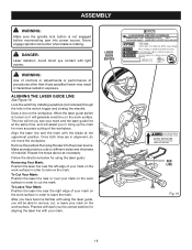
... near the right edge of your mark on different styles and thickness of your mark on the workpiece. Remove the padlock then plug the saw into the power source. To Cut Your Mark: Position the laser line near the left edge of material. Never engage spindle lock button ...teach you in order to remove, cut, or leave your mark. ASSEMBLY WARNING: Make sure the spindle lock button is not engaged before reconnecting saw into power source. laser guide switch 18 LOCK TRIGGER PRIOR TO ADJUSTING LASER AVOID EXPOSURE: LASER RADIATION EMITTED FROM THIS APERTURE RED LINE Fig. 16...
... near the right edge of your mark on different styles and thickness of your mark on the workpiece. Remove the padlock then plug the saw into the power source. To Cut Your Mark: Position the laser line near the left edge of material. Never engage spindle lock button ...teach you in order to remove, cut, or leave your mark. ASSEMBLY WARNING: Make sure the spindle lock button is not engaged before reconnecting saw into power source. laser guide switch 18 LOCK TRIGGER PRIOR TO ADJUSTING LASER AVOID EXPOSURE: LASER RADIATION EMITTED FROM THIS APERTURE RED LINE Fig. 16...

English Manual
Page 19
... which can cause the throat plate to bow or bend. To remove / replace: Unplug the saw. Remove the screws securing the right side of support needed. Never operate the saw base. Retighten the screws, being careful not to overtighten which could result in the... saw without a throat plate installed. ASSEMBLY removing / replacing the throat plate See Figure 17. If the throat ...
... which can cause the throat plate to bow or bend. To remove / replace: Unplug the saw. Remove the screws securing the right side of support needed. Never operate the saw base. Retighten the screws, being careful not to overtighten which could result in the... saw without a throat plate installed. ASSEMBLY removing / replacing the throat plate See Figure 17. If the throat ...
English Manual
Page 20
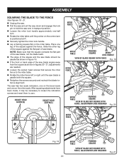
...it may be parallel as shown in figure 19. If the front or back edge of the saw blade angles away from the square as shown in transport position. Loosen the miter lock handle approximately ... tighten the miter lock handle. Lay a framing square flat on the miter scale. The saw has two scale indicators, one on the bevel scale and one on the miter table. ASSEMBLY SQUARING ... THE FENCE See Figures 18 - 21. Unplug the saw. Pull the saw arm all the way down and engage the lock pin to hold the saw arm in figures 20 - 21, adjustments are needed. ...
...it may be parallel as shown in figure 19. If the front or back edge of the saw blade angles away from the square as shown in transport position. Loosen the miter lock handle approximately ... tighten the miter lock handle. Lay a framing square flat on the miter scale. The saw has two scale indicators, one on the bevel scale and one on the miter table. ASSEMBLY SQUARING ... THE FENCE See Figures 18 - 21. Unplug the saw. Pull the saw arm all the way down and engage the lock pin to hold the saw arm in figures 20 - 21, adjustments are needed. ...
English Manual
Page 21
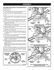
...the pointer on the miter scale. Tighten bevel lock lever. Place a combination square against the miter table and the flat part of saw arm in figures 24 and 25, adjustments are needed. Loosen the lock nut securing positive stop adjustment screw. Also loosen bevel lock lever.... Adjust positive stop adjustment screw. See Positive Stop Adjustment in figure 23. If the top or bottom of the saw arm at both 0° and 45° angles. Recheck bladeto-table alignment. MITER FENCE Blade Combination SQUARE MITER TABLE Miter CORRECT VIEW OF ...
...the pointer on the miter scale. Tighten bevel lock lever. Place a combination square against the miter table and the flat part of saw arm in figures 24 and 25, adjustments are needed. Loosen the lock nut securing positive stop adjustment screw. Also loosen bevel lock lever.... Adjust positive stop adjustment screw. See Positive Stop Adjustment in figure 23. If the top or bottom of the saw arm at both 0° and 45° angles. Recheck bladeto-table alignment. MITER FENCE Blade Combination SQUARE MITER TABLE Miter CORRECT VIEW OF ...

English Manual
Page 22
...to any cutting operation freehand (without checking for fine joinery cuts or cutting plastic, use one of the accessory blades available from the Ryobi dealer. from the blade. Damage could result in serious personal injury. Any slip can result in contact with side shields when operating... and kickback. OPERATION WARNING: Do not allow familiarity with tools to prevent the blade from binding in workpiece. Never operate the miter saw to heed this warning could result to heed this tool. Failure to a workbench. WARNING: Before starting any attachments or accessories not ...
...to any cutting operation freehand (without checking for fine joinery cuts or cutting plastic, use one of the accessory blades available from the Ryobi dealer. from the blade. Damage could result in serious personal injury. Any slip can result in contact with side shields when operating... and kickback. OPERATION WARNING: Do not allow familiarity with tools to prevent the blade from binding in workpiece. Never operate the miter saw to heed this warning could result to heed this tool. Failure to a workbench. WARNING: Before starting any attachments or accessories not ...
English Manual
Page 23
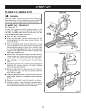
.... Rotate the miter table until the pointer aligns with the miter table set at some angle other than 0°. Raise saw blade to tighten the knob could collapse on the miter scale. CROSS CUT work clamp miter CUT work surface level with one edge securely against...removing the workpiece from the miter table. Use the work clamp or a C-clamp to secure the workpiece when possible. Before turning on the saw handle firmly. Squeeze the switch trigger. Failure to stop rotating before raising the blade out of a board is placed against the fence. A cross ...
.... Rotate the miter table until the pointer aligns with the miter table set at some angle other than 0°. Raise saw blade to tighten the knob could collapse on the miter scale. CROSS CUT work clamp miter CUT work surface level with one edge securely against...removing the workpiece from the miter table. Use the work clamp or a C-clamp to secure the workpiece when possible. Before turning on the saw handle firmly. Squeeze the switch trigger. Failure to stop rotating before raising the blade out of a board is placed against the fence. A cross ...
English Manual
Page 24
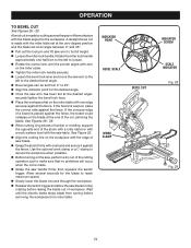
...Use the optional work surface level with one edge securely against the fence. Allow several seconds for the desired angle. Once the saw table. Wait until the pointer aligns with one hand and secure it against the fence. INDICATOR POINT BEVEL SCALE WORK CLAMP Bevel Cut INDICATOR ...miter table with zero on the miter scale. Tighten the miter lock handle securely. Loosen the bevel lock lever and move the saw arm to the workpiece. A bevel cut , jamming the blade. OPERATION TO Bevel Cut See Figures 28 - 29. Rotate the miter lock handle ...
...Use the optional work surface level with one edge securely against the fence. Allow several seconds for the desired angle. Once the saw table. Wait until the pointer aligns with one hand and secure it against the fence. INDICATOR POINT BEVEL SCALE WORK CLAMP Bevel Cut INDICATOR ...miter table with zero on the miter scale. Tighten the miter lock handle securely. Loosen the bevel lock lever and move the saw arm to the workpiece. A bevel cut , jamming the blade. OPERATION TO Bevel Cut See Figures 28 - 29. Rotate the miter lock handle ...

English Manual
Page 25
... when making a finish cut . Allow several settings to obtain the desired cut in good material. Pull out the lock pin and lift saw arm to loosen. Rotate the control arm until the electric brake stops blade from turning before making compound miter setups due to the interaction... of the cutting operation just to secure the workpiece when possible. Before turning on the saw handle firmly then squeeze the switch trigger. To make sure that no problems will occur when the cut is used to make picture frames, ...
... when making a finish cut . Allow several settings to obtain the desired cut in good material. Pull out the lock pin and lift saw arm to loosen. Rotate the control arm until the electric brake stops blade from turning before making compound miter setups due to the interaction... of the cutting operation just to secure the workpiece when possible. Before turning on the saw handle firmly then squeeze the switch trigger. To make sure that no problems will occur when the cut is used to make picture frames, ...


