
English Manual
Page 4
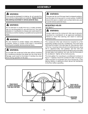
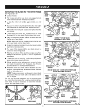
..., gasoline, petroleum-based products, or any operation. Never use a clean cloth when cleaning. Have defective switches replaced by securely tightening the miter lock levers. The maximum blade capacity of personal injury. Inspect for and remove all adjustments are included with your tool to be clamped. ...height. KEEP HANDS AWAY FROM CUTTING AREA. Stay constantly aware of drugs, alcohol, or any operation freehand. If it firmly against the fence as a backstop. Repair or replace a damaged or worn cord immediately. Do not rush. DO NOT USE TOOL IF SWITCH DOES ...
..., gasoline, petroleum-based products, or any operation. Never use a clean cloth when cleaning. Have defective switches replaced by securely tightening the miter lock levers. The maximum blade capacity of personal injury. Inspect for and remove all adjustments are included with your tool to be clamped. ...height. KEEP HANDS AWAY FROM CUTTING AREA. Stay constantly aware of drugs, alcohol, or any operation freehand. If it firmly against the fence as a backstop. Repair or replace a damaged or worn cord immediately. Do not rush. DO NOT USE TOOL IF SWITCH DOES ...
English Manual
Page 9
Compound Cut A cross cut made across the grain or the width of the workpiece pushed into the blade or being guided by a fence, miter gauge, or other aids. Cutter Head (planers and jointers) A rotating piece of the workpiece. FPM or SPM Feet per minute (or strokes ...; to prevent kickback. Ripping or Rip Cut A cutting operation along the length of adjustable blades. As it securely against the table or fence during a ripping operation. Miter Cut A cutting operation made at 90°. Snipe (planers) Depression made with the blade at any angle to stop the workpiece from...
Compound Cut A cross cut made across the grain or the width of the workpiece pushed into the blade or being guided by a fence, miter gauge, or other aids. Cutter Head (planers and jointers) A rotating piece of the workpiece. FPM or SPM Feet per minute (or strokes ...; to prevent kickback. Ripping or Rip Cut A cutting operation along the length of adjustable blades. As it securely against the table or fence during a ripping operation. Miter Cut A cutting operation made at 90°. Snipe (planers) Depression made with the blade at any angle to stop the workpiece from...
English Manual
Page 10
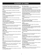
... Maximum nominal lumber sizes 2 x 6 Cutting Capacity with Miter at 45°/Bevel 45°: Maximum nominal lumber sizes 2 x 4 blade wrench Upper Blade Guard "D" Handle DUST BAG Bevel Lock Knob Bevel Scale MITER Fence Miter Table BASE Switch Trigger Lower blade guard throat plate "NO... HANDS ZONE" LABEL "NO HANDS ZONE" BOUNDARY LINE Miter Scale MITER LOCK PLATE CONTROL ARM Positive Stop(s) WORK CLAMP 10 Miter Lock Handle Fig. 1 FEATURES PRODUCT SPECIFICATIONS...
... Maximum nominal lumber sizes 2 x 6 Cutting Capacity with Miter at 45°/Bevel 45°: Maximum nominal lumber sizes 2 x 4 blade wrench Upper Blade Guard "D" Handle DUST BAG Bevel Lock Knob Bevel Scale MITER Fence Miter Table BASE Switch Trigger Lower blade guard throat plate "NO... HANDS ZONE" LABEL "NO HANDS ZONE" BOUNDARY LINE Miter Scale MITER LOCK PLATE CONTROL ARM Positive Stop(s) WORK CLAMP 10 Miter Lock Handle Fig. 1 FEATURES PRODUCT SPECIFICATIONS...
English Manual
Page 11
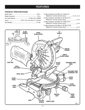
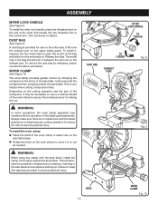
...LASER GUIDE For more accurate cuts, a laser guide is also larger providing additional support. 11 Saw Arm Lock Pin mITER LOCK HANDLE recessed area Saw arm Locked in . MITER FENCE The miter fence on each side of the saw . The left side is included with the saw See Figure 2. Positive stop blade... well as a knowledge of servicing. 10 in the saw . It is made . BEVEL LOCK KNOB The bevel lock knob securely locks the compound miter saw has a powerful 14 amp motor with all cuts. CARRYING the saw . When used properly, the laser guide makes accurate, precision cutting simple ...
...LASER GUIDE For more accurate cuts, a laser guide is also larger providing additional support. 11 Saw Arm Lock Pin mITER LOCK HANDLE recessed area Saw arm Locked in . MITER FENCE The miter fence on each side of the saw . The left side is included with the saw See Figure 2. Positive stop blade... well as a knowledge of servicing. 10 in the saw . It is made . BEVEL LOCK KNOB The bevel lock knob securely locks the compound miter saw has a powerful 14 amp motor with all cuts. CARRYING the saw . When used properly, the laser guide makes accurate, precision cutting simple ...
English Manual
Page 14
...or create accessories not recommended for use with this warning can result in a hazardous condition leading to the blade if it strikes the miter fence during use to a work surface before operating. Each of sufficient length to heed this tool. Bolts should be of the four ... warning could result in serious personal injury. The hole pattern for interference between the blade and the miter fence. Carefully check the workbench after mounting to make sure the compound miter saw to a workbench is misuse and could result in serious personal injury. Any such alteration or ...
...or create accessories not recommended for use with this warning can result in a hazardous condition leading to the blade if it strikes the miter fence during use to a work surface before operating. Each of sufficient length to heed this tool. Bolts should be of the four ... warning could result in serious personal injury. The hole pattern for interference between the blade and the miter fence. Carefully check the workbench after mounting to make sure the compound miter saw to a workbench is misuse and could result in serious personal injury. Any such alteration or ...
English Manual
Page 15
... to the fence or the saw . A dust bag is provided for emptying, simply reverse the above procedure. DUST BAG See Figure 9. Depending on the same side as needed. To install it on the end of the blade guard assembly. Always make sure there is very helpful when cutting compound miters. This is...
... to the fence or the saw . A dust bag is provided for emptying, simply reverse the above procedure. DUST BAG See Figure 9. Depending on the same side as needed. To install it on the end of the blade guard assembly. Always make sure there is very helpful when cutting compound miters. This is...
English Manual
Page 18
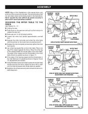
... right until the pointer on the miter table. Framing MITER Square FENCE MITER TABLE Miter lock plate throat plate Miter lock Handle VIEW OF MITER TABLE SQUARE WITH FENCE Fig. 14 Framing Square MITER FENCE MITER TABLE Miter lock plate throat plate VIEW OF MITER TABLE NOT SQUARE WITH FENCE, ADJUSTMENTS ARE REQUIRED Fig. 15 Framing Square MITER FENCE MITER TABLE Miter lock plate throat plate VIEW OF...
... right until the pointer on the miter table. Framing MITER Square FENCE MITER TABLE Miter lock plate throat plate Miter lock Handle VIEW OF MITER TABLE SQUARE WITH FENCE Fig. 14 Framing Square MITER FENCE MITER TABLE Miter lock plate throat plate VIEW OF MITER TABLE NOT SQUARE WITH FENCE, ADJUSTMENTS ARE REQUIRED Fig. 15 Framing Square MITER FENCE MITER TABLE Miter lock plate throat plate VIEW OF...
English Manual
Page 19
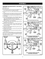
... Screw(s) Socket Head Screw(s) MITER FENCE Blade Miter lock plate MITER TABLE FRAMING Miter SQUARE lock Handle VIEW OF Blade SQUARE WITH FENCE Fig. 18 MITER FENCE Blade Miter lock plate MITER TABLE FRAMING SQUARE Miter lock Handle VIEW OF Blade NOT SQUARE WITh FENCE, ADJUSTMENTS ARE REQUIRED Fig. 19 MITER FENCE Blade FENCE Fig. 17 Miter lock plate MITER TABLE FRAMING SQUARE Miter lock Handle VIEW OF...
... Screw(s) Socket Head Screw(s) MITER FENCE Blade Miter lock plate MITER TABLE FRAMING Miter SQUARE lock Handle VIEW OF Blade SQUARE WITH FENCE Fig. 18 MITER FENCE Blade Miter lock plate MITER TABLE FRAMING SQUARE Miter lock Handle VIEW OF Blade NOT SQUARE WITh FENCE, ADJUSTMENTS ARE REQUIRED Fig. 19 MITER FENCE Blade FENCE Fig. 17 Miter lock plate MITER TABLE FRAMING SQUARE Miter lock Handle VIEW OF...
English Manual
Page 20
... miter table). BEVEL LOCK KNOB miter FENCE Blade Miter lock plate Combination SQUARE MITER TABLE Miter lock Handle CORRECT VIEW OF Blade SQUARE WITH Miter Table Fig. 22 BEVEL LOCK KNOB miter FENCE Blade Miter lock plate Combination SQUARE MITER TABLE Miter lock Handle VIEW OF Blade NOT SQUARe WITH Miter Table, ADJUSTMENTS ARE REQUIRED Fig. 23 BEVEL LOCK KNOB miter FENCE Blade Miter lock plate Miter...
... miter table). BEVEL LOCK KNOB miter FENCE Blade Miter lock plate Combination SQUARE MITER TABLE Miter lock Handle CORRECT VIEW OF Blade SQUARE WITH Miter Table Fig. 22 BEVEL LOCK KNOB miter FENCE Blade Miter lock plate Combination SQUARE MITER TABLE Miter lock Handle VIEW OF Blade NOT SQUARe WITH Miter Table, ADJUSTMENTS ARE REQUIRED Fig. 23 BEVEL LOCK KNOB miter FENCE Blade Miter lock plate Miter...

English Manual
Page 21
...available from the Ryobi dealer. The workpiece must remain free on the floor or in serious personal injury. The workpiece binding the blade will cause motor stalling and kickback. APPLICATIONS You may use one side of the blade only. Rotate the miter lock handle ... not recommended by cutting across the grain of this tool. The use any cutting operation freehand (without holding workpiece against the fence). Never operate the miter saw to heed this tool for picture frames mold- Failure to a workbench. for the following purposes: Crosscutting wood...
...available from the Ryobi dealer. The workpiece must remain free on the floor or in serious personal injury. The workpiece binding the blade will cause motor stalling and kickback. APPLICATIONS You may use one side of the blade only. Rotate the miter lock handle ... not recommended by cutting across the grain of this tool. The use any cutting operation freehand (without holding workpiece against the fence). Never operate the miter saw to heed this tool for picture frames mold- Failure to a workbench. for the following purposes: Crosscutting wood...
English Manual
Page 22
...the workpiece flat on the blade at the end of the positive stop notches, located in the miter table frame. Tighten the miter lock handle securely. The 45° triangle on the miter fence provides for the maximum clearance required for the desired angle. Once the saw arm to... the left to loosen. Press the miter lock plate down with thumb and hold. Rotate the control arm until the ...
...the workpiece flat on the blade at the end of the positive stop notches, located in the miter table frame. Tighten the miter lock handle securely. The 45° triangle on the miter fence provides for the maximum clearance required for the desired angle. Once the saw arm to... the left to loosen. Press the miter lock plate down with thumb and hold. Rotate the control arm until the ...
English Manual
Page 23
... the bevel lock knob. Recheck miter angle setting. A compound miter cut is warped, place the convex side against the fence. The first angle setting should always be set from miter table. If the board is a cut the control arm on the miter table with sloping sides, and for a particular... a board could collapse on the workpiece with one hand and secure it against the fence. Rotate the miter lock handle approximately one-half turn to the left to its full height. Loosen the miter lock handle. See Figure 30. Align the cutting line on the blade...
... the bevel lock knob. Recheck miter angle setting. A compound miter cut is warped, place the convex side against the fence. The first angle setting should always be set from miter table. If the board is a cut the control arm on the miter table with sloping sides, and for a particular... a board could collapse on the workpiece with one hand and secure it against the fence. Rotate the miter lock handle approximately one-half turn to the left to its full height. Loosen the miter lock handle. See Figure 30. Align the cutting line on the blade...
English Manual
Page 24
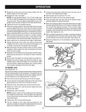
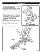
...61550; Before turning on the base of workpiece. Use the optional work clamp or a C-clamp to secure the workpiece. 45° x 45° COMPOUND MITER CUT Fig. 29 Long workpiece Workpiece supports 24 Fig. 30 Allow several seconds for the blade to make sure that no problems will occur when... and allow the saw and work table during the cutting operation. Long workpieces need extra supports. Wait until the electric brake stops blade from miter table. OPERATION Grasp the stock firmly with one hand and secure it does not sag. The support should be placed along the ...
...61550; Before turning on the base of workpiece. Use the optional work clamp or a C-clamp to secure the workpiece. 45° x 45° COMPOUND MITER CUT Fig. 29 Long workpiece Workpiece supports 24 Fig. 30 Allow several seconds for the blade to make sure that no problems will occur when... and allow the saw and work table during the cutting operation. Long workpieces need extra supports. Wait until the electric brake stops blade from miter table. OPERATION Grasp the stock firmly with one hand and secure it does not sag. The support should be placed along the ...
English Manual
Page 26
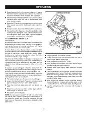
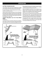
...corner Top edge against fence = LEFT SIDE, INSIDE CORNER RIGHT SIDE, OUTSIDE CORNER MITER Table Fence outside corner, lay the molding with its broad back surface flat on the miter table and against fence = RIGHT SIDE, INSIDE CORNER LEFT SIDE, OUTSIDE CORNER MITER Table crown molding flat ...interdependent; In order to fine tune your miter saw does an excellent job of your settings. Laying molding flat on scrap molding. OPERATION cutting crown molding The compound miter saw . 52° 38° ceiling w a l l Fence inside or outside corner BOTTOM edge against ...
...corner Top edge against fence = LEFT SIDE, INSIDE CORNER RIGHT SIDE, OUTSIDE CORNER MITER Table Fence outside corner, lay the molding with its broad back surface flat on the miter table and against fence = RIGHT SIDE, INSIDE CORNER LEFT SIDE, OUTSIDE CORNER MITER Table crown molding flat ...interdependent; In order to fine tune your miter saw does an excellent job of your settings. Laying molding flat on scrap molding. OPERATION cutting crown molding The compound miter saw . 52° 38° ceiling w a l l Fence inside or outside corner BOTTOM edge against ...

English Manual
Page 27
... set right 31.62° 3. x 6 in., boards should be clamped with the convex side against fence 2. Miter table set left end of cut Left side, outside corner 1. When cutting warped material, always make sure it will pinch the blade near the completion... right end of cut Right side, outside corner 1. If the warped material is positioned on the miter table with a C-clamp as shown in figure 32. Bottom edge of molding against the fence. Top edge of molding against fence 2. WRONG Fig. 33 WARNING: To avoid a kickback and to avoid serious personal injury, never ...
... set right 31.62° 3. x 6 in., boards should be clamped with the convex side against fence 2. Miter table set left end of cut Left side, outside corner 1. When cutting warped material, always make sure it will pinch the blade near the completion... right end of cut Right side, outside corner 1. If the warped material is positioned on the miter table with a C-clamp as shown in figure 32. Bottom edge of molding against the fence. Top edge of molding against fence 2. WRONG Fig. 33 WARNING: To avoid a kickback and to avoid serious personal injury, never ...
Repair Sheet
Page 5
... 089100212705 * Screw (M4 x 8 mm, Flat Hd 4 42 518106300 Throat Plate (Table Insert 1 43 A07003100256 Miter Table 1 44 089100207113 Fence 1 987000329 Safety Guard 1 8-05-08 (Rev:01) DESCRIPTION QTY. * Screw (M4 x 9 mm, Pan Hd...25 mm 2 * Blade Wrench (M35 x 115 mm 1 Operator's Manual * Standard Hardware Item - RYOBI 10 in all correspondence regarding your MITER SAW or when ordering repair parts. Always mention the model number in . KEY PART NO. May Be...DESCRIPTION QTY. MODEL NUMBER TS1342L The model number will be found on a plate attached to the motor housing.
... 089100212705 * Screw (M4 x 8 mm, Flat Hd 4 42 518106300 Throat Plate (Table Insert 1 43 A07003100256 Miter Table 1 44 089100207113 Fence 1 987000329 Safety Guard 1 8-05-08 (Rev:01) DESCRIPTION QTY. * Screw (M4 x 9 mm, Pan Hd...25 mm 2 * Blade Wrench (M35 x 115 mm 1 Operator's Manual * Standard Hardware Item - RYOBI 10 in all correspondence regarding your MITER SAW or when ordering repair parts. Always mention the model number in . KEY PART NO. May Be...DESCRIPTION QTY. MODEL NUMBER TS1342L The model number will be found on a plate attached to the motor housing.


