
Operation Manual
Page 2
...; All assembly must have proper training and experience. TABLE OF CONTENTS Rules for Safe Assembly...2 Symbols...3 Tools Needed...3 Unpacking...4 Loose Parts List...5 Assembly...6-7 Final Preparation...8 RULES FOR SAFE ASSEMBLY WARNING: Strictly adhere to do so could cause serious personal injury.
...; All assembly must have proper training and experience. TABLE OF CONTENTS Rules for Safe Assembly...2 Symbols...3 Tools Needed...3 Unpacking...4 Loose Parts List...5 Assembly...6-7 Final Preparation...8 RULES FOR SAFE ASSEMBLY WARNING: Strictly adhere to do so could cause serious personal injury.
Operation Manual
Page 4
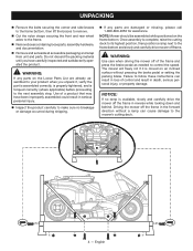
... can result in loss of control and result in serious personal injury. n Remove and set aside all accessible packaging and wrap from unit and parts. WARNING: Use care when driving the mower off frame. n Cut the nylon straps securing the front and rear wheel axles to remove. UNPACKING...n Remove the bolts securing the corner and side braces to the frame bottom, then lift the braces to the frame. n If any parts on the Loose Parts List are damaged or missing, please call 1-800-860-4050 for assistance. Once assembly is torqued correctly (where applicable) before proceeding to the ...
... can result in loss of control and result in serious personal injury. n Remove and set aside all accessible packaging and wrap from unit and parts. WARNING: Use care when driving the mower off frame. n Cut the nylon straps securing the front and rear wheel axles to remove. UNPACKING...n Remove the bolts securing the corner and side braces to the frame bottom, then lift the braces to the frame. n If any parts on the Loose Parts List are damaged or missing, please call 1-800-860-4050 for assistance. Once assembly is torqued correctly (where applicable) before proceeding to the ...
Operation Manual
Page 5
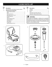
...Operator's Manual (Not Shown 1 WARNING: If any parts are replaced with damaged, missing, or incorrect parts could result in serious personal injury. 1. 2. 3.... 4. 5. 5 - Description Qty. 1 Seat Assembly with Safety Interlock Cable.......... 1 2 Steering Column Assembly Upper Steering Shaft 1 Bolts 2 Steering Column 1 Steering Column Cover 1 Flange Washers 2 Spring 1 Steering Wheel Hub 1 Steering Wheel 1 Flat Washer 1 Flange Nut 1 Steering Wheel Cover 1 Key No. LOOSE PARTS LIST...
...Operator's Manual (Not Shown 1 WARNING: If any parts are replaced with damaged, missing, or incorrect parts could result in serious personal injury. 1. 2. 3.... 4. 5. 5 - Description Qty. 1 Seat Assembly with Safety Interlock Cable.......... 1 2 Steering Column Assembly Upper Steering Shaft 1 Bolts 2 Steering Column 1 Steering Column Cover 1 Flange Washers 2 Spring 1 Steering Wheel Hub 1 Steering Wheel 1 Flat Washer 1 Flange Nut 1 Steering Wheel Cover 1 Key No. LOOSE PARTS LIST...

Parts Diagram
Page 10
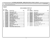
FIGURE F DECK ASSEMBLY PARTS LIST KEY PART NO. NUMBER DESCRIPTION QTY 16 996265001 Front Deck Roller Wheel (124.5 Dia 2 17 994869001 Mulching Blade 2 18 996256001 Blade Holder 2 19 996039001 Deck Bagger Chute ... 2 12 996356001 Cotter Pin (10 mm 4 13 996262001 Lifting Plate Pin 2 14 996251001 Flange Lock Nut (M6 x 1.00 16 15 994903001 Motor Cover 2 KEY PART NO. RY48110, RY48111, RY48112 The model number will be found on a label under the seat. Always mention the model number in all correspondence regarding your LAWN MOWER...
FIGURE F DECK ASSEMBLY PARTS LIST KEY PART NO. NUMBER DESCRIPTION QTY 16 996265001 Front Deck Roller Wheel (124.5 Dia 2 17 994869001 Mulching Blade 2 18 996256001 Blade Holder 2 19 996039001 Deck Bagger Chute ... 2 12 996356001 Cotter Pin (10 mm 4 13 996262001 Lifting Plate Pin 2 14 996251001 Flange Lock Nut (M6 x 1.00 16 15 994903001 Motor Cover 2 KEY PART NO. RY48110, RY48111, RY48112 The model number will be found on a label under the seat. Always mention the model number in all correspondence regarding your LAWN MOWER...
Parts Diagram 1
Page 10
FIGURE F DECK ASSEMBLY PARTS LIST KEY PART NO. 48 V RIDING LAWN MOWER − MODEL NOS. NUMBER DESCRIPTION QTY 1 994867001 Flange Nut (M8 x 1.25 2 2 996291001 Screw (M4.2 x 13 mm 4 3 994791001 Carriage Bolt (M6 x ... (M6 x 1.00 16 15 994903001 Motor Cover 2 16 996265001 Front Deck Roller Wheel (124.5 Dia 2 KEY PART NO. Always mention the model number in all correspondence regarding your LAWN MOWER or when ordering replacement parts. RY48110, RY48111, RY48112 The model number will be found on a label under the seat. NUMBER DESCRIPTION QTY 17...
FIGURE F DECK ASSEMBLY PARTS LIST KEY PART NO. 48 V RIDING LAWN MOWER − MODEL NOS. NUMBER DESCRIPTION QTY 1 994867001 Flange Nut (M8 x 1.25 2 2 996291001 Screw (M4.2 x 13 mm 4 3 994791001 Carriage Bolt (M6 x ... (M6 x 1.00 16 15 994903001 Motor Cover 2 16 996265001 Front Deck Roller Wheel (124.5 Dia 2 KEY PART NO. Always mention the model number in all correspondence regarding your LAWN MOWER or when ordering replacement parts. RY48110, RY48111, RY48112 The model number will be found on a label under the seat. NUMBER DESCRIPTION QTY 17...

