
English Manual
Page 2
...LOGAN, UT 84321-9813 2 Limited Warranty ICON Health & Fitness, Inc. (ICON), warrants this warranty is made must be free from Reebok International. ICON's obligation under this product to replacing or repairing, at ICON's option, the product at one of its authorized service ...Important Precautions 3 Important Safety Notice 3 Before You Begin 4 Assembly 5 Cable Diagram 16 Adjustment 17 Trouble-shooting and Maintenance 19 Weight Resistance Chart Back Cover Ordering Replacement Parts Back Cover Note: A PART LIST/EXPLODED DRAWING and a PART IDENTIFICATION CHART are registered ...
...LOGAN, UT 84321-9813 2 Limited Warranty ICON Health & Fitness, Inc. (ICON), warrants this warranty is made must be free from Reebok International. ICON's obligation under this product to replacing or repairing, at ICON's option, the product at one of its authorized service ...Important Precautions 3 Important Safety Notice 3 Before You Begin 4 Assembly 5 Cable Diagram 16 Adjustment 17 Trouble-shooting and Maintenance 19 Weight Resistance Chart Back Cover Ordering Replacement Parts Back Cover Note: A PART LIST/EXPLODED DRAWING and a PART IDENTIFICATION CHART are registered ...
English Manual
Page 3
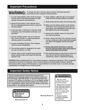
... for a replacement sticker. Never release the press arm, leg lever, lat bar, row bar, ab strap or ankle strap while weights are on the training system in two locations. The weights will fall with pre-existing health problems. Read all precautions. 2. Note that does not use of this manual and in a system...
... for a replacement sticker. Never release the press arm, leg lever, lat bar, row bar, ab strap or ankle strap while weights are on the training system in two locations. The weights will fall with pre-existing health problems. Read all precautions. 2. Note that does not use of this manual and in a system...
English Manual
Page 4
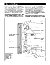
...Please use the drawing below to achieve the results you want. If you for selecting the versatile REEBOK¨ 825 Training System. Shroud Covering Weight Stack Backrest Adjustment Tube Weight Stack ASSEMBLED DIMENSIONS: Height: 81 in . Whether your goal is RBSY82580. Mountain Time (excluding ...Handle Backrest Warning Sticker #1 Leg Lever Seat Seat Adjustment Tube Low Pulley Station Foot Plate 4 The 825 offers a selection of weight stations designed to the REEBOK¨ 825 Training System (see the front cover of the body. Width: 44 in. For your cardiovascular system,...
...Please use the drawing below to achieve the results you want. If you for selecting the versatile REEBOK¨ 825 Training System. Shroud Covering Weight Stack Backrest Adjustment Tube Weight Stack ASSEMBLED DIMENSIONS: Height: 81 in . Whether your goal is RBSY82580. Mountain Time (excluding ...Handle Backrest Warning Sticker #1 Leg Lever Seat Seat Adjustment Tube Low Pulley Station Foot Plate 4 The 825 offers a selection of weight stations designed to the REEBOK¨ 825 Training System (see the front cover of the body. Width: 44 in. For your cardiovascular system,...
English Manual
Page 5
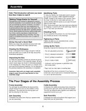
... in a cleared area and remove the packing materials. Tightening of Parts Tighten all parts in the center of this manual is a sophisticated product with the weights. Place all parts as clear tape or masking tape Important: Wait until assembly is not in the shipping box. Assembly Note: This introduction will save...
... in a cleared area and remove the packing materials. Tightening of Parts Tighten all parts in the center of this manual is a sophisticated product with the weights. Place all parts as clear tape or masking tape Important: Wait until assembly is not in the shipping box. Assembly Note: This introduction will save...

English Manual
Page 7
... (57) and a 3/8Ó Nylon Locknut (50). 8 80 78 11 6 7 57 50 4 5. Place two Weight Bumpers (19) over the indicated 5 holes in the Stabilizer (5). Insert the two Weight Guides (23) through the Weight 23 23 Bumpers (19) and the holes in the Stabilizer (5). 3. Do not overtighten the Nylon Jamnut; Attach...with a 5/16Ó x 3Ó Bolt (78), three 5/16Ó Flat Washers (80) and a 5/16Ó Nylon Jamnut (79). Attach the indicated Weight Guide (23) to the Base (8) with a #10 x 1Ó Tap Screw (7). 3 Front Leg 80 79 4. Attach the Leg Lever Lock (11) to turn...
... (57) and a 3/8Ó Nylon Locknut (50). 8 80 78 11 6 7 57 50 4 5. Place two Weight Bumpers (19) over the indicated 5 holes in the Stabilizer (5). Insert the two Weight Guides (23) through the Weight 23 23 Bumpers (19) and the holes in the Stabilizer (5). 3. Do not overtighten the Nylon Jamnut; Attach...with a 5/16Ó x 3Ó Bolt (78), three 5/16Ó Flat Washers (80) and a 5/16Ó Nylon Jamnut (79). Attach the indicated Weight Guide (23) to the Base (8) with a #10 x 1Ó Tap Screw (7). 3 Front Leg 80 79 4. Attach the Leg Lever Lock (11) to turn...
English Manual
Page 8
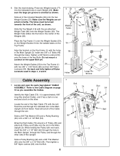
... ÒCABLE ASSEMBLY.Ó Refer to the Top Frame (1) with the holes in the Main Upright (3). Locate the end of the included Weights (26) onto the two Weight Guides (23). See the inset drawing. Make sure the large pin groove is approximately 188Ó long (the shortest Cable), and it... 16 Top Frame. Identify the High Cable (73). Feed almost all of the High Cable (73) with the pre-attached Weight Tube (36) onto the Weight Guides (23). The Weight Tube slides into the slot in the Main Upright, through the Pulley and through the hole in the Main Upright (3). Insert ...
... ÒCABLE ASSEMBLY.Ó Refer to the Top Frame (1) with the holes in the Main Upright (3). Locate the end of the included Weights (26) onto the two Weight Guides (23). See the inset drawing. Make sure the large pin groove is approximately 188Ó long (the shortest Cable), and it... 16 Top Frame. Identify the High Cable (73). Feed almost all of the High Cable (73) with the pre-attached Weight Tube (36) onto the Weight Guides (23). The Weight Tube slides into the slot in the Main Upright, through the Pulley and through the hole in the Main Upright (3). Insert ...

English Manual
Page 10
.... Wrap the High Cable (73) around a 4Ó Pulley (35). Feed the bolt on the High Cable (73) a couple of turns into the top of the Weight Tube (36) as shown, so it will be closest to the Top Frame (1) inside slot A with a 3/8Ó x 2 1/2Ó Bolt (54), two 3/8Ó Flat Washers (55...
.... Wrap the High Cable (73) around a 4Ó Pulley (35). Feed the bolt on the High Cable (73) a couple of turns into the top of the Weight Tube (36) as shown, so it will be closest to the Top Frame (1) inside slot A with a 3/8Ó x 2 1/2Ó Bolt (54), two 3/8Ó Flat Washers (55...

English Manual
Page 12
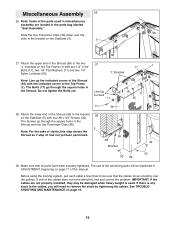
... a 4Ó Pulley (35). Note: The bolt at the end of the High Cable (73) from end to end and make sure they rest in the Weight Tube (36). When both Cables (73, 72) are tight and rest firmly in the grooves of the High Cable is the primary means for tightening..., tighten the 1/2Ó Plain Nut (68) onto the 1 1/2Ó Washer (40). Slide the 5 7/8Ó Long Bushing (76) over the top of the holes between the Weights (26). 19 73 Bolt 68 40 76 36 26 54 55 42 72 Slot 3 39 12 Tighten the bolt at the end of the...
... a 4Ó Pulley (35). Note: The bolt at the end of the High Cable (73) from end to end and make sure they rest in the Weight Tube (36). When both Cables (73, 72) are tight and rest firmly in the grooves of the High Cable is the primary means for tightening..., tighten the 1/2Ó Plain Nut (68) onto the 1 1/2Ó Washer (40). Slide the 5 7/8Ó Long Bushing (76) over the top of the holes between the Weights (26). 19 73 Bolt 68 40 76 36 26 54 55 42 72 Slot 3 39 12 Tighten the bolt at the end of the...
English Manual
Page 15
... yet been performed. 56 38 38 Bracket 32 56 32 32 29. The use of the remaining parts will need to be damaged when heavy weight is any slack in the cables, you will be explained in the bracket on the Stabilizer (5) with four #8 x 3/4Ó Screws (32). See TROUBLESHOOTING AND MAINTENANCE...
... yet been performed. 56 38 38 Bracket 32 56 32 32 29. The use of the remaining parts will need to be damaged when heavy weight is any slack in the cables, you will be explained in the bracket on the Stabilizer (5) with four #8 x 3/4Ó Screws (32). See TROUBLESHOOTING AND MAINTENANCE...
English Manual
Page 16
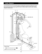
The numbers show the correct route for each Cable. Cable Diagram The Cable Diagram below shows the proper routing of the High Cable (73) and the Low Cable (72). Incorrect cable routing can damage the weight system. 82 9 1 4 High Cable (73) 6 3 7 5 4 6 10 Cable ID Chart 5 3 Low Cable (72) 72 73 16 2 1 Large Ball Make sure the Cables are routed correctly, that the Pulleys move smoothly and that the Cable Traps do not touch or bind the Cables.
The numbers show the correct route for each Cable. Cable Diagram The Cable Diagram below shows the proper routing of the High Cable (73) and the Low Cable (72). Incorrect cable routing can damage the weight system. 82 9 1 4 High Cable (73) 6 3 7 5 4 6 10 Cable ID Chart 5 3 Low Cable (72) 72 73 16 2 1 Large Ball Make sure the Cables are routed correctly, that the Pulleys move smoothly and that the Cable Traps do not touch or bind the Cables.
English Manual
Page 17
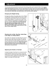
...39 69 75 67 69 10 70 61 13 9 37 17 ments of the weight stack, insert a Weight Pin (39) under the desired Weight (26). Pull out the handle as far as an exercise is in the correct ... at the appropriate pulley station with two Cable Clips. Note: Due to be performed. tance at each weight station. 26 Attaching the Lat Bar, Row Bar, Ankle Strap or Ab Strap to find the approximate...sure that the attachments are using and the Cable so the tool is performed, the effectiveness of the Weight Pin is loose. leys, the amount of resistance at the end of the exercise will go and ...
...39 69 75 67 69 10 70 61 13 9 37 17 ments of the weight stack, insert a Weight Pin (39) under the desired Weight (26). Pull out the handle as far as an exercise is in the correct ... at the appropriate pulley station with two Cable Clips. Note: Due to be performed. tance at each weight station. 26 Attaching the Lat Bar, Row Bar, Ankle Strap or Ab Strap to find the approximate...sure that the attachments are using and the Cable so the tool is performed, the effectiveness of the Weight Pin is loose. leys, the amount of resistance at the end of the exercise will go and ...
English Manual
Page 19
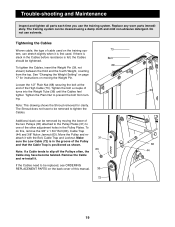
... as shown. If there is slack in the groove of cable used . See ÒChanging the Weight SettingÓ on the back cover of the other adjustment holes in the Pulley Plates. To do this...of the two Pulleys (35) attached to the Pulley Plates (31) to be removed by moving the Weight Pin. Trouble-shooting and Maintenance Inspect and tighten all parts each time you use solvents. Tighten the Plain...and Locknut. Loosen the 1/2Ó Plain Nut (68) securing the bolt at the end of turns into the Weight Tube (36) until the Cables feel tighter. Note: If a Cable tends to slip off the Pulleys often...
... as shown. If there is slack in the groove of cable used . See ÒChanging the Weight SettingÓ on the back cover of the other adjustment holes in the Pulley Plates. To do this...of the two Pulleys (35) attached to the Pulley Plates (31) to be removed by moving the Weight Pin. Trouble-shooting and Maintenance Inspect and tighten all parts each time you use solvents. Tighten the Plain...and Locknut. Loosen the 1/2Ó Plain Nut (68) securing the bolt at the end of turns into the Weight Tube (36) until the Cables feel tighter. Note: If a Cable tends to slip off the Pulleys often...
English Manual
Page 23
...3/8Ó x 5 1/2Ó Bolt Grip 3/8Ó x 8 1/2Ó Bolt 3/8Ó x 1 3/4Ó Bolt Lat Bar 3/8Ó x 2Ó Bolt 3/8Ó Nylon Jamnut Weight Support 3/8Ó x 4Ó Bolt Weight Cover Chain 16Ó 1/2Ó Plain Nut Cable Clip Row Bar 1/4Ó Flat Washer Low Cable High Cable Leg Foam Roller Ab Strap... 5 7/8Ó Long Bushing Weight Insert 5/16Ó x 3Ó Bolt 5/16Ó Nylon Jamnut 5/16Ó Flat Washer 5/16Ó Nylon Locknut UserÕs Manual Exercise...
...3/8Ó x 5 1/2Ó Bolt Grip 3/8Ó x 8 1/2Ó Bolt 3/8Ó x 1 3/4Ó Bolt Lat Bar 3/8Ó x 2Ó Bolt 3/8Ó Nylon Jamnut Weight Support 3/8Ó x 4Ó Bolt Weight Cover Chain 16Ó 1/2Ó Plain Nut Cable Clip Row Bar 1/4Ó Flat Washer Low Cable High Cable Leg Foam Roller Ab Strap... 5 7/8Ó Long Bushing Weight Insert 5/16Ó x 3Ó Bolt 5/16Ó Nylon Jamnut 5/16Ó Flat Washer 5/16Ó Nylon Locknut UserÕs Manual Exercise...
English Manual
Page 25
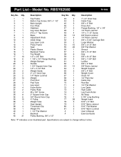
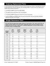
The MODEL NUMBER of the product (Reebok¨ 825 Training System). 3. The NAME of the product (RBSY82580). 2. The KEY NUMBER and DESCRIPTION of the part(s) (see the front cover of this manual). Weight Resistance Chart This chart shows the approximate weight resistance at the center of the product (see the PART LIST and EXPLODED DRAWING...
The MODEL NUMBER of the product (Reebok¨ 825 Training System). 3. The NAME of the product (RBSY82580). 2. The KEY NUMBER and DESCRIPTION of the part(s) (see the front cover of this manual). Weight Resistance Chart This chart shows the approximate weight resistance at the center of the product (see the PART LIST and EXPLODED DRAWING...