PLR44MU Manual 1
Page 2
... out screw before installation......... 3 DIN Front-Mount (Method A 3 Installing the unit 3 Removing the unit 4 DIN Rear-Mount (Method B 5 Using the detachable front panel ...... 6 Wiring Connection 7 Operation 8 Location of keys 8 Switching on/off the unit 9 ...
... out screw before installation......... 3 DIN Front-Mount (Method A 3 Installing the unit 3 Removing the unit 4 DIN Rear-Mount (Method B 5 Using the detachable front panel ...... 6 Wiring Connection 7 Operation 8 Location of keys 8 Switching on/off the unit 9 ...
PLR44MU Manual 1
Page 3
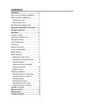
... the antenna. 3. Then slide the sleeve off , and then disconnect the cable from "Front" (conventional DIN Front-mount) or "Rear" (DIN Rear-mount installation, utilizing threaded screw holes at the middle left and right sides of the unit. L Key Outer Trim Ring Sleeve Front Panel R Key 3 DIN FRONT/REAR...-MOUNT This unit can remove it. INSTALLATION Notes: Choose the mounting location where the unit will go (with the notches facing up properly and the unit and the system work properly...
... the antenna. 3. Then slide the sleeve off , and then disconnect the cable from "Front" (conventional DIN Front-mount) or "Rear" (DIN Rear-mount installation, utilizing threaded screw holes at the middle left and right sides of the unit. L Key Outer Trim Ring Sleeve Front Panel R Key 3 DIN FRONT/REAR...-MOUNT This unit can remove it. INSTALLATION Notes: Choose the mounting location where the unit will go (with the notches facing up properly and the unit and the system work properly...
PLR44MU Manual 1
Page 4
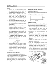
.... 5. Use the screw holes marked T (Toyota), N (Nissan) located on both of the unit to the mounting bolt on the back of "installing the front panel"). Reconnect the wire harness and the antenna and be most effective. Reconnect the cable to attach the other long threading Removing the...of the outer trim ring then pull it out to secure the sleeve in place. Bending open the tabs located around the sleeve with a screwdriver. INSTALLATION 6. Mount the sleeve by inserting the sleeve into place. 9. To further secure the unit, use the supplied hardware (Tapping Screw (5x25mm) and...
.... 5. Use the screw holes marked T (Toyota), N (Nissan) located on both of the unit to the mounting bolt on the back of "installing the front panel"). Reconnect the wire harness and the antenna and be most effective. Reconnect the cable to attach the other long threading Removing the...of the outer trim ring then pull it out to secure the sleeve in place. Bending open the tabs located around the sleeve with a screwdriver. INSTALLATION 6. Mount the sleeve by inserting the sleeve into place. 9. To further secure the unit, use the supplied hardware (Tapping Screw (5x25mm) and...
PLR44MU Manual 1
Page 5
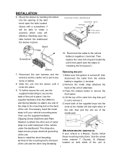
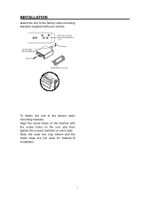
INSTALLATION fasten the unit to the factory radio mounting brackets. Align the screw holes on each side. Note: the outer trim ring, sleeve and the metal strap are not used for method B installation. 5 Factory Radio Mounting Bracket Screw Side View showing Screw Holes marked T, N Screw Dashboard or Console To fasten the unit to the factory radio mounting brackets supplied with the screw holes on the unit, and then tighten the screws (5x5mm) on the bracket with your vehicle.
INSTALLATION fasten the unit to the factory radio mounting brackets. Align the screw holes on each side. Note: the outer trim ring, sleeve and the metal strap are not used for method B installation. 5 Factory Radio Mounting Bracket Screw Side View showing Screw Holes marked T, N Screw Dashboard or Console To fasten the unit to the factory radio mounting brackets supplied with the screw holes on the unit, and then tighten the screws (5x5mm) on the bracket with your vehicle.
PLR44MU Manual 1
Page 6
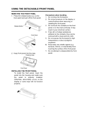
... contacts, they can be removed with a clean and dry cloth. 5. Otherwise, abnormality occurs on the display or control buttons when removing or installing the front panel. 3. Precautions when handling 1. Do not put pressure on the display or some keys will not function properly. 6 Press the... release button ( ) on the main unit body. Keep front panel into the housing and make sure the panel is properly installed. Do not attempt to high temperatures or direct sunlight in poor electrical contact. 4. benzene, thinner, or insecticides) from touching the surface of...
... contacts, they can be removed with a clean and dry cloth. 5. Otherwise, abnormality occurs on the display or control buttons when removing or installing the front panel. 3. Precautions when handling 1. Do not put pressure on the display or some keys will not function properly. 6 Press the... release button ( ) on the main unit body. Keep front panel into the housing and make sure the panel is properly installed. Do not attempt to high temperatures or direct sunlight in poor electrical contact. 4. benzene, thinner, or insecticides) from touching the surface of...
PLR44MU Manual 1
Page 9
... (24) to select the desired adjustment mode. If any button is pressed in the mute state, the mute state is effect during SEEK operation. Initial installation of strong station, and a distant setting for the following order: →BAS‐TRE‐BAL‐FAD‐LOUD‐EQ‐DX‐...
... (24) to select the desired adjustment mode. If any button is pressed in the mute state, the mute state is effect during SEEK operation. Initial installation of strong station, and a distant setting for the following order: →BAS‐TRE‐BAL‐FAD‐LOUD‐EQ‐DX‐...
