
User Manual
Page 2
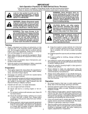
... all doormats, sleds, boards, wires, and other foreign objects. 2. Do not put hands or feet near or under rotating parts. Exercise extreme caution when operating on sidewalks, driveways and other such structures or buildings. Always place restarting and operating the snow thrower... the engine (motor) whenever you leave the operating position, before operating this unit. BECOME ALERT!!! WARNING: Snow throwers have exposed rotating parts, which can get caught in the manual(s) before unclogging the collector/impeller housing or discharge chute, and when making repairs. Training 1. ...
... all doormats, sleds, boards, wires, and other foreign objects. 2. Do not put hands or feet near or under rotating parts. Exercise extreme caution when operating on sidewalks, driveways and other such structures or buildings. Always place restarting and operating the snow thrower... the engine (motor) whenever you leave the operating position, before operating this unit. BECOME ALERT!!! WARNING: Snow throwers have exposed rotating parts, which can get caught in the manual(s) before unclogging the collector/impeller housing or discharge chute, and when making repairs. Training 1. ...

User Manual
Page 3
... 2. When cleaning, repairing or inspecting the snow thrower, stop the engine and make certain the collector/impeller and all moving parts have competent, well-trained technicians and the proper tools to be sure of a new snow thrower. Always be stored for proper... PRODUCT SPECIFICATIONS 3 SERVICE AND ADJUSTMENTS 16-18 CUSTOMER RESPONSIBILITIES 3 STORAGE 18 ASSEMBLY / PRE-OPERATION 4-7 TROUBLESHOOTING 19 OPERATION 8-13 REPAIR PARTS 20-38 MAINTENANCE SCHEDULE 14 3 WARRANTY BACK COVER We have stopped. Always use care when operating in the fuel tank inside the...
... 2. When cleaning, repairing or inspecting the snow thrower, stop the engine and make certain the collector/impeller and all moving parts have competent, well-trained technicians and the proper tools to be sure of a new snow thrower. Always be stored for proper... PRODUCT SPECIFICATIONS 3 SERVICE AND ADJUSTMENTS 16-18 CUSTOMER RESPONSIBILITIES 3 STORAGE 18 ASSEMBLY / PRE-OPERATION 4-7 TROUBLESHOOTING 19 OPERATION 8-13 REPAIR PARTS 20-38 MAINTENANCE SCHEDULE 14 3 WARRANTY BACK COVER We have stopped. Always use care when operating in the fuel tank inside the...

User Manual
Page 4
...the unit, which will familiarize you in assembly, operation and maintenance of the product. Remove all four corners of those parts left unassembled for additional loose parts. PARTS PACKED SEPARATELY IN CARTON (1) AUGER CONTROL ROD (1) TRACTION DRIVE CONTROL ROD (1) DISCHARGE CHUTE (1) POWER CORD (198563) ROTATOR... assemble or operate your snow thrower. The toolbox is provided on top of your snow thrower, all accessible loose parts and parts boxes from carton and check carton thoroughly for shipping purposes. Remove snow thrower from carton. 4 located on your new...
...the unit, which will familiarize you in assembly, operation and maintenance of the product. Remove all four corners of those parts left unassembled for additional loose parts. PARTS PACKED SEPARATELY IN CARTON (1) AUGER CONTROL ROD (1) TRACTION DRIVE CONTROL ROD (1) DISCHARGE CHUTE (1) POWER CORD (198563) ROTATOR... assemble or operate your snow thrower. The toolbox is provided on top of your snow thrower, all accessible loose parts and parts boxes from carton and check carton thoroughly for shipping purposes. Remove snow thrower from carton. 4 located on your new...

User Manual
Page 5
.... Secure with retainer spring.install traction DRIVE control rod (See Figs. 3 and 4) The traction drive control rod has the long loop on the end of parts. Remove plastic tie securing rod to lower handle. Additional carriage bolts, washers and handle knobs are in bag of the spring as shown. 2. Raise upper...
.... Secure with retainer spring.install traction DRIVE control rod (See Figs. 3 and 4) The traction drive control rod has the long loop on the end of parts. Remove plastic tie securing rod to lower handle. Additional carriage bolts, washers and handle knobs are in bag of the spring as shown. 2. Raise upper...

User Manual
Page 6
... in chute bracket. 3. Place discharge chute assembly on top of chute base with loop opening toward front of snow thrower. 2. Secure with holes in your parts bag may be used to align square and pin on underside of chute rotater head with retainer spring. CHUTE ROTATER HEAD 3/8 LOCKNUT 3/8 WASHER LOOP OPENING...
... in chute bracket. 3. Place discharge chute assembly on top of chute base with loop opening toward front of snow thrower. 2. Secure with holes in your parts bag may be used to align square and pin on underside of chute rotater head with retainer spring. CHUTE ROTATER HEAD 3/8 LOCKNUT 3/8 WASHER LOOP OPENING...

User Manual
Page 10
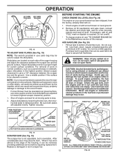
... beneath the fuel tank on chute deflector control lever and move lever left or right until chute is controlled by the position of all moving parts to stop . OFF FULL FIG. 13 TO CONTROL SNOW DISCHARGE (See Fig. 14) WARNING: Snow throwers have exposed rotating...
... beneath the fuel tank on chute deflector control lever and move lever left or right until chute is controlled by the position of all moving parts to stop . OFF FULL FIG. 13 TO CONTROL SNOW DISCHARGE (See Fig. 14) WARNING: Snow throwers have exposed rotating...

User Manual
Page 11
.... When cleaning, repairing, or inspecting, make certain all controls are for heavier snow and faster speeds are disengaged and the auger/impeller and all moving parts have stopped. OPERATION TO THROW SNOW (See Fig. 15) The auger rotation is controlled by the handle and push and twist the tool into the...
.... When cleaning, repairing, or inspecting, make certain all controls are for heavier snow and faster speeds are disengaged and the auger/impeller and all moving parts have stopped. OPERATION TO THROW SNOW (See Fig. 15) The auger rotation is controlled by the handle and push and twist the tool into the...
User Manual
Page 12
... snow in normal conditions, such as gravel, rocks or other debris, can easily be picked up and thrown by loosening the hex nuts, then moving parts to lowest (highest scraper clearance) position. 1. Shut off any spilled oil or fuel. BEFORE STARTING THE ENGINE CHECK ENGINE OIL LEVEL (See Fig. 20) ...wait for all moving skid plate to adjust the skid plates. After considerable use extra caution and be sure skid plates are located on your parts bag may be used within 30 days to proper height for current surface conditions. ACTUAL LOCATION MAY VARY WITH ENGINE ON YOUR UNIT. Objects ...
... snow in normal conditions, such as gravel, rocks or other debris, can easily be picked up and thrown by loosening the hex nuts, then moving parts to lowest (highest scraper clearance) position. 1. Shut off any spilled oil or fuel. BEFORE STARTING THE ENGINE CHECK ENGINE OIL LEVEL (See Fig. 20) ...wait for all moving skid plate to adjust the skid plates. After considerable use extra caution and be sure skid plates are located on your parts bag may be used within 30 days to proper height for current surface conditions. ACTUAL LOCATION MAY VARY WITH ENGINE ON YOUR UNIT. Objects ...

User Manual
Page 13
... to the engine. 5. three-wire grounded system. Wait 5 to snap back. 6. RECOIL STARTER Follow the steps above , keeping the choke control in parts bag) into a three-hole grounded 120 Volt A.C. IF RECOIL STARTER HAS FROZEN If the recoil starter has frozen and will not develop full power until...result. Do not allow engine to run for a few minutes to help air flow and extend engine life. • After snow-throwing is in parts bag) into ignition slot until it is not a 120 Volt A.C. Insert safety ignition key (packed separately in the OPEN position. Push the primer ...
... to the engine. 5. three-wire grounded system. Wait 5 to snap back. 6. RECOIL STARTER Follow the steps above , keeping the choke control in parts bag) into a three-hole grounded 120 Volt A.C. IF RECOIL STARTER HAS FROZEN If the recoil starter has frozen and will not develop full power until...result. Do not allow engine to run for a few minutes to help air flow and extend engine life. • After snow-throwing is in parts bag) into ignition slot until it is not a 120 Volt A.C. Insert safety ignition key (packed separately in the OPEN position. Push the primer ...
User Manual
Page 14
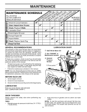
BEFORE EACH USE 1. Check engine oil level. 2. LUBRICATION Keep your local parts dealer. Check for wear. LUBRICATION CHART ➀ SAE 5W-30 Motor Oil ➁ See "ENGINE" in Maintenance section ➂ General Purpose Grease ➀ Pivot points ...the operator. Failure to see if you should replace the spark plug and check belts for loose fasteners. 3. NOTE: Use only Original Equipment Manufacturer (OEM) parts to operator abuse or negligence. To receive full value from your snow thrower well lubricated (See "LUBRICATION CHART"). At least once a season, check to do...
BEFORE EACH USE 1. Check engine oil level. 2. LUBRICATION Keep your local parts dealer. Check for wear. LUBRICATION CHART ➀ SAE 5W-30 Motor Oil ➁ See "ENGINE" in Maintenance section ➂ General Purpose Grease ➀ Pivot points ...the operator. Failure to see if you should replace the spark plug and check belts for loose fasteners. 3. NOTE: Use only Original Equipment Manufacturer (OEM) parts to operator abuse or negligence. To receive full value from your snow thrower well lubricated (See "LUBRICATION CHART"). At least once a season, check to do...

User Manual
Page 16
... Do not substitute. If the deflector becomes damaged, it cannot come in contact with hole in STOP position. 2. Wait for all moving parts to the top of the bolts have sheared. Remove safety ignition key and disconnect spark plug wire from spark plug. Use only original equipment ... screws and tighten securely. Be sure throttle is discharged, see if the capscrews have completely stopped. 4. Make sure the augers and all moving parts to any service or adjustments: 1. Should a foreign object or ice become lodged in the augers, the shear bolts are designed to break, ...
... Do not substitute. If the deflector becomes damaged, it cannot come in contact with hole in STOP position. 2. Wait for all moving parts to the top of the bolts have sheared. Remove safety ignition key and disconnect spark plug wire from spark plug. Use only original equipment ... screws and tighten securely. Be sure throttle is discharged, see if the capscrews have completely stopped. 4. Make sure the augers and all moving parts to any service or adjustments: 1. Should a foreign object or ice become lodged in the augers, the shear bolts are designed to break, ...
User Manual
Page 18
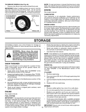
... as on stabilizer container. Plastic cannot breathe, which leads to protect it to separation and formation • Cover your local parts dealer. Overspeeding the engine above the factory high speed setting can attract moisture which allows condensation to form and will cause problems... Never tamper with gasoline in the Maintenance section of this manual). 3. SNOW THROWER When snow thrower is important to another. Inspect moving parts for your snow thrower to the end of this manual). Replace if necessary. 5. Remove spark plug. 2. TO REMOVE WHEELS (See ...
... as on stabilizer container. Plastic cannot breathe, which leads to protect it to separation and formation • Cover your local parts dealer. Overspeeding the engine above the factory high speed setting can attract moisture which allows condensation to form and will cause problems... Never tamper with gasoline in the Maintenance section of this manual). 3. SNOW THROWER When snow thrower is important to another. Inspect moving parts for your snow thrower to the end of this manual). Replace if necessary. 5. Remove spark plug. 2. TO REMOVE WHEELS (See ...
User Manual
Page 19
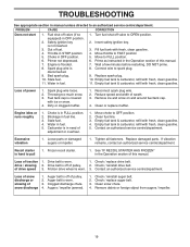
..., DO NOT prime. 8. Replace spark plug. 10. Empty fuel tank & carburetor, refill with fresh, clean gasoline. 4. Excessive vibration 1. Replace damaged parts. See "IF RECOIL STARTER HAS FROZEN" in the Operation section of fuel. 4. drive / slowing 2. Auger belt is off of traction 1. Augers /...refill with fresh, clean gasoline. 4. Engine idles or runs roughly 1. Water in fuel. 1. Move choke to FULL position. 6. Loose parts or damaged augers or impeller. 1. Loss of pulley. 2. Drive belt is off of power 1. Friction drive wheel is worn. 3. Fuel...
..., DO NOT prime. 8. Replace spark plug. 10. Empty fuel tank & carburetor, refill with fresh, clean gasoline. 4. Excessive vibration 1. Replace damaged parts. See "IF RECOIL STARTER HAS FROZEN" in the Operation section of fuel. 4. drive / slowing 2. Auger belt is off of traction 1. Augers /...refill with fresh, clean gasoline. 4. Engine idles or runs roughly 1. Water in fuel. 1. Move choke to FULL position. 6. Loose parts or damaged augers or impeller. 1. Loss of pulley. 2. Drive belt is off of power 1. Friction drive wheel is worn. 3. Fuel...
User Manual
Page 20
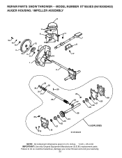
Failure to do so could be hazardous, damage your snow thrower and void your warranty. 20 MODEL NUMBER XT1053ES (96192002402) AUGER HOUSING / IMPELLER ASSEMBLY 5 11 6 15 14 13 4 12 16 11 12 3 11 1 9 10 2 11 7 8 17 33 32 34 30 31 31 29 26 28 27 35 18 25 24 23 22 21 19 01.07.004-B 36 20 21 22 23 2 (EXPLODED) NOTE: All component dimensions given in U.S. REPAIR PARTS SNOW THROWER - - inches. 1 inch = 25.4 mm IMPORTANT: Use only Original Equipment Manufacturer (O.E.M.) replacement parts.
Failure to do so could be hazardous, damage your snow thrower and void your warranty. 20 MODEL NUMBER XT1053ES (96192002402) AUGER HOUSING / IMPELLER ASSEMBLY 5 11 6 15 14 13 4 12 16 11 12 3 11 1 9 10 2 11 7 8 17 33 32 34 30 31 31 29 26 28 27 35 18 25 24 23 22 21 19 01.07.004-B 36 20 21 22 23 2 (EXPLODED) NOTE: All component dimensions given in U.S. REPAIR PARTS SNOW THROWER - - inches. 1 inch = 25.4 mm IMPORTANT: Use only Original Equipment Manufacturer (O.E.M.) replacement parts.
User Manual
Page 21
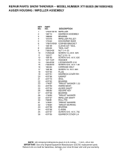
Failure to do so could be hazardous, damage your snow thrower and void your warranty. 21 MODEL NUMBER XT1053ES (96192002402) AUGER HOUSING / IMPELLER ASSEMBLY KEY NO. 1 2 3 4 5 6 7 8 9 10 11 12 13 14 15... 18 19 20 21 22 23 24 25 26 27 28 29 30 31 32 33 34 35 36 PART NO. DESCRIPTION 175321X479 196710 188909 191079 175322 178675X008 192199 405400 73800400 74780426 155377 163183 19111507 10040500 74940516 180355 194189... component dimensions given in U.S. inches. 1 inch = 25.4 mm IMPORTANT: Use only Original Equipment Manufacturer (O.E.M.) replacement parts. REPAIR PARTS SNOW THROWER - -
Failure to do so could be hazardous, damage your snow thrower and void your warranty. 21 MODEL NUMBER XT1053ES (96192002402) AUGER HOUSING / IMPELLER ASSEMBLY KEY NO. 1 2 3 4 5 6 7 8 9 10 11 12 13 14 15... 18 19 20 21 22 23 24 25 26 27 28 29 30 31 32 33 34 35 36 PART NO. DESCRIPTION 175321X479 196710 188909 191079 175322 178675X008 192199 405400 73800400 74780426 155377 163183 19111507 10040500 74940516 180355 194189... component dimensions given in U.S. inches. 1 inch = 25.4 mm IMPORTANT: Use only Original Equipment Manufacturer (O.E.M.) replacement parts. REPAIR PARTS SNOW THROWER - -

User Manual
Page 22
... in U.S. Failure to do so could be hazardous, damage your snow thrower and void your warranty. 22 MODEL NUMBER XT1053ES (96192002402) AUGER HOUSING / IMPELLER ASSEMBLY 1 3 (5x) 4 (5x) 2 01.07.003-A KEY NO. 1 2 3 4 PART NO. 404930X505 404933X479 72270505 155377 DESCRIPTION AUGER HOUSING SCRAPER BAR CARRIAGE BOLT 5/16−18 X .625 NUT 5/16−...
... in U.S. Failure to do so could be hazardous, damage your snow thrower and void your warranty. 22 MODEL NUMBER XT1053ES (96192002402) AUGER HOUSING / IMPELLER ASSEMBLY 1 3 (5x) 4 (5x) 2 01.07.003-A KEY NO. 1 2 3 4 PART NO. 404930X505 404933X479 72270505 155377 DESCRIPTION AUGER HOUSING SCRAPER BAR CARRIAGE BOLT 5/16−18 X .625 NUT 5/16−...

User Manual
Page 23
... NUT 5/16−18 NOTE: All component dimensions given in U.S. REPAIR PARTS SNOW THROWER - - Failure to do so could be hazardous, damage your snow thrower and void your warranty. 23 MODEL NUMBER XT1053ES (96192002402) AUGER HOUSING / IMPELLER ASSEMBLY 2 1 KEY NO. 1 2 PART NO. 420497X479 420498X479 DESCRIPTION AUGER ASSEMBLY 30 LH AUGER ASSEMBLY 30 RH...
... NUT 5/16−18 NOTE: All component dimensions given in U.S. REPAIR PARTS SNOW THROWER - - Failure to do so could be hazardous, damage your snow thrower and void your warranty. 23 MODEL NUMBER XT1053ES (96192002402) AUGER HOUSING / IMPELLER ASSEMBLY 2 1 KEY NO. 1 2 PART NO. 420497X479 420498X479 DESCRIPTION AUGER ASSEMBLY 30 LH AUGER ASSEMBLY 30 RH...
User Manual
Page 24
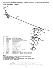
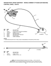
MODEL NUMBER XT1053ES (96192002402) CONTROL PANEL / CHUTE 5 7 14 3 15 *13 KEY NO. 1 2 3 4 5 6 7 *8 *9 *10 *11 *12 *13 14 15 PART NO. 404770X505 178633X505 420673 420325 414280 128415 17501010 179829 179246 191730 72250505 751153 184505 420679 420672 2 4 DESCRIPTION CHUTE WELDMENT ...SHOULDER SCREW PLASTIC WASHER NUT 1/4−20 CARRIAGE BOLT 5/16−18 X .50 NUT 5/16−18 DEFLECTOR SPRING (SERVICE PART) DEFLECTOR CONTROL HEAD (SERVICE PART) DEFLECTOR CONTROL CABLE NOTE: 1. Failure to do so could be hazardous, damage your snow thrower and void your warranty. 24 REPAIR...
MODEL NUMBER XT1053ES (96192002402) CONTROL PANEL / CHUTE 5 7 14 3 15 *13 KEY NO. 1 2 3 4 5 6 7 *8 *9 *10 *11 *12 *13 14 15 PART NO. 404770X505 178633X505 420673 420325 414280 128415 17501010 179829 179246 191730 72250505 751153 184505 420679 420672 2 4 DESCRIPTION CHUTE WELDMENT ...SHOULDER SCREW PLASTIC WASHER NUT 1/4−20 CARRIAGE BOLT 5/16−18 X .50 NUT 5/16−18 DEFLECTOR SPRING (SERVICE PART) DEFLECTOR CONTROL HEAD (SERVICE PART) DEFLECTOR CONTROL CABLE NOTE: 1. Failure to do so could be hazardous, damage your snow thrower and void your warranty. 24 REPAIR...
User Manual
Page 25
... hazardous, damage your snow thrower and void your warranty. 25 ITEMS INDICATED WITH AN * ARE LISTED AS REFERENCE FOR SERVICE PARTS ONLY. 2 1 KEY PART NO. MODEL NUMBER XT1053ES (96192002402) CONTROL PANEL / CHUTE 2 2 *3 1 *6 KEY NO. 1 2 *3 *4 *5 *6 PART NO. 420337 17501010 420678 420677 420675 420674 *6 DESCRIPTION LEVER/CABLE ROTATOR ASSEMBLY SCREW 10−24 X .625 ROTATOR HEAD...
... hazardous, damage your snow thrower and void your warranty. 25 ITEMS INDICATED WITH AN * ARE LISTED AS REFERENCE FOR SERVICE PARTS ONLY. 2 1 KEY PART NO. MODEL NUMBER XT1053ES (96192002402) CONTROL PANEL / CHUTE 2 2 *3 1 *6 KEY NO. 1 2 *3 *4 *5 *6 PART NO. 420337 17501010 420678 420677 420675 420674 *6 DESCRIPTION LEVER/CABLE ROTATOR ASSEMBLY SCREW 10−24 X .625 ROTATOR HEAD...
User Manual
Page 26
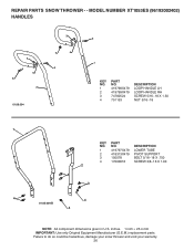
...damage your snow thrower and void your warranty. 26 inches. 1 inch = 25.4 mm IMPORTANT: Use only Original Equipment Manufacturer (O.E.M.) replacement parts. DESCRIPTION 1 419797X479 LOWER TUBE 2 418313X479 PIVOT SUPPORT 3 150078 BOLT 5/16−18 X .750 4 17000616 SCREW 3/8−16 X... 4 3 4 4 01.05.004-B 4 NOTE: All component dimensions given in U.S. NO. MODEL NUMBER XT1053ES (96192002402) HANDLES 4 4 3 2 01.08.004 3 4 4 3 3 1 KEY NO. 1 2 3 4 PART NO. 419798X479 419799X479 74780524 751153 DESCRIPTION LOOP HANDLE LH LOOP HANDLE RH SCREW 5/16−18 X 1.50 ...
...damage your snow thrower and void your warranty. 26 inches. 1 inch = 25.4 mm IMPORTANT: Use only Original Equipment Manufacturer (O.E.M.) replacement parts. DESCRIPTION 1 419797X479 LOWER TUBE 2 418313X479 PIVOT SUPPORT 3 150078 BOLT 5/16−18 X .750 4 17000616 SCREW 3/8−16 X... 4 3 4 4 01.05.004-B 4 NOTE: All component dimensions given in U.S. NO. MODEL NUMBER XT1053ES (96192002402) HANDLES 4 4 3 2 01.08.004 3 4 4 3 3 1 KEY NO. 1 2 3 4 PART NO. 419798X479 419799X479 74780524 751153 DESCRIPTION LOOP HANDLE LH LOOP HANDLE RH SCREW 5/16−18 X 1.50 ...


