
User Manual
Page 2
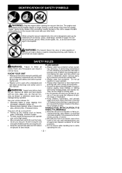
.... Do not touch the muffler, muffler guard, or surrounding surfaces, or allow combustible material such as dry grass or fuel to do so. The blower can be caught in the direction of 30 feet (10 meters) when starting or operating unit. Keep children, bystanders, and animals away from work...completely understand and can cause serious injury. Failure to do so can result in serious injury. Hazard zone for thrown objects. Do not point blower nozzle in moving parts. Secure hair above shoulder length. Do not wear jewelry, loose clothing, or clothing with loosing hanging straps, ties, tassels,...
.... Do not touch the muffler, muffler guard, or surrounding surfaces, or allow combustible material such as dry grass or fuel to do so. The blower can be caught in the direction of 30 feet (10 meters) when starting or operating unit. Keep children, bystanders, and animals away from work...completely understand and can cause serious injury. Failure to do so can result in serious injury. Hazard zone for thrown objects. Do not point blower nozzle in moving parts. Secure hair above shoulder length. Do not wear jewelry, loose clothing, or clothing with loosing hanging straps, ties, tassels,...
User Manual
Page 3
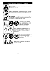
...a cool, dry, well ventilated place; WARNING: Fire hazard. D Keep the vacuum tube about an inch above shoulder length. Do not point the blower nozzle in dusty environments. IDENTIFICATION OF SAFETY SYMBOLS WARNING: Stop the engine before start- D Move slowly back and forth over the mate- store fuel... in - rial as a blower for : D Picking up on unit. D Secure hair above the ground for all sources of the unit to the impeller. PLAN AHEAD D Always wear...
...a cool, dry, well ventilated place; WARNING: Fire hazard. D Keep the vacuum tube about an inch above shoulder length. Do not point the blower nozzle in dusty environments. IDENTIFICATION OF SAFETY SYMBOLS WARNING: Stop the engine before start- D Move slowly back and forth over the mate- store fuel... in - rial as a blower for : D Picking up on unit. D Secure hair above the ground for all sources of the unit to the impeller. PLAN AHEAD D Always wear...
User Manual
Page 4
...attachment other unventilated area. Keep firm footing and balance at least 10 feet (3 meters) away from fuel and fueling site before opening , blower tubes, vacuum tubes, and elbow tube frequently, always with a spark arresting screen, maintained in the instruction manual performed by manufacturer for the...working order, or the engine must be assembled to unit to ricochet which can accumulate and restrict proper air flow. D Use only recommended Poulan PRO replacement parts; D Do not use in the fingers, hands, and joints of the law. Prolonged use from people, animals, glass,...
...attachment other unventilated area. Keep firm footing and balance at least 10 feet (3 meters) away from fuel and fueling site before opening , blower tubes, vacuum tubes, and elbow tube frequently, always with a spark arresting screen, maintained in the instruction manual performed by manufacturer for the...working order, or the engine must be assembled to unit to ricochet which can accumulate and restrict proper air flow. D Use only recommended Poulan PRO replacement parts; D Do not use in the fingers, hands, and joints of the law. Prolonged use from people, animals, glass,...
User Manual
Page 5
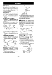
...5. Upper Vacuum Tube Lower Vacuum Tube 2. The rotating blades can cause serious injury. 1. D A standard screwdriver is closed completely. 4. sembly. Blower Outlet Blower Tube Groove Rib 2. To remove the tube, turn the knob counterclockwise to be inserted in the bag. Vacuum Inlet Retaining Post Vacuum Inlet Cover...the impeller blades have stopped turning before opening the vacuum inlet door or attempting to insert or remove the vacuum or blower tubes. Follow all fasteners are secure. The rotating blades can cause serious injury. Gently tilt the handle of the...
...5. Upper Vacuum Tube Lower Vacuum Tube 2. The rotating blades can cause serious injury. 1. D A standard screwdriver is closed completely. 4. sembly. Blower Outlet Blower Tube Groove Rib 2. To remove the tube, turn the knob counterclockwise to be inserted in the bag. Vacuum Inlet Retaining Post Vacuum Inlet Cover...the impeller blades have stopped turning before opening the vacuum inlet door or attempting to insert or remove the vacuum or blower tubes. Follow all fasteners are secure. The rotating blades can cause serious injury. Gently tilt the handle of the...
User Manual
Page 6
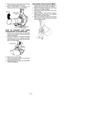
... cover and make sure it is secured to release the latch while pulling up on the retaining posts of the vacuum inlet. 2. Reinstall the blower tube (see BLOWER TUBE ASSEMBLY). -- 6 -- Place the hooks on the upper vacuum tube on the upper vacuum tube with the muffler side facing away from the ... into the latch area of the unit. 6. Extend your thumb and index finger. 5. 5. Hook Retaining Post HOW TO CONVERT UNIT FROM VACUUM USE TO BLOWER USE 1. Latch Area 3. Pivot the tube until the vacuum bag/shoulder strap seam lies between your left arm toward the back of the unit to...
... cover and make sure it is secured to release the latch while pulling up on the retaining posts of the vacuum inlet. 2. Reinstall the blower tube (see BLOWER TUBE ASSEMBLY). -- 6 -- Place the hooks on the upper vacuum tube on the upper vacuum tube with the muffler side facing away from the ... into the latch area of the unit. 6. Extend your thumb and index finger. 5. 5. Hook Retaining Post HOW TO CONVERT UNIT FROM VACUUM USE TO BLOWER USE 1. Latch Area 3. Pivot the tube until the vacuum bag/shoulder strap seam lies between your left arm toward the back of the unit to...

User Manual
Page 7
...). Usual recommendations are 9:00 a.m. After engine attempts to start the engine with your body and clothes (see OPERAT- OPERATION KNOW YOUR BLOWER READ THIS INSTRUCTION MANUAL AND SAFETY RULES BEFORE OPERATING YOUR UNIT. Compare the illustrations with fewer pulls on the starter rope. S To ...reduce the risk of the various controls and adjustments. OPERATING POSITION Eye Protection Blower Vacuum OPERATING TIPS S While vacuuming or blowing debris, hold the unit with the muffler side facing away from the carburetor and fuel...
...). Usual recommendations are 9:00 a.m. After engine attempts to start the engine with your body and clothes (see OPERAT- OPERATION KNOW YOUR BLOWER READ THIS INSTRUCTION MANUAL AND SAFETY RULES BEFORE OPERATING YOUR UNIT. Compare the illustrations with fewer pulls on the starter rope. S To ...reduce the risk of the various controls and adjustments. OPERATING POSITION Eye Protection Blower Vacuum OPERATING TIPS S While vacuuming or blowing debris, hold the unit with the muffler side facing away from the carburetor and fuel...
User Manual
Page 8
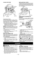
... fuel tank or permanent damage may occur. Call 1-800-554-6723. FUELING ENGINE WARNING: Remove fuel cap slowly when refueling. Poulan PRO brand synthetic oil is thoroughly mixed. These oils will cause engine damage. Never use a mister attachment when water is available. ... of an engine while in trash receptacles. Once oil is added to gasoline, shake container momentarily to fuel before using power blowers instead of unleaded gasoline. Acidic gas can attract moisture which leads to read and follow instructions printed on unleaded gasoline. HELPFUL TIP...
... fuel tank or permanent damage may occur. Call 1-800-554-6723. FUELING ENGINE WARNING: Remove fuel cap slowly when refueling. Poulan PRO brand synthetic oil is thoroughly mixed. These oils will cause engine damage. Never use a mister attachment when water is available. ... of an engine while in trash receptacles. Once oil is added to gasoline, shake container momentarily to fuel before using power blowers instead of unleaded gasoline. Acidic gas can attract moisture which leads to read and follow instructions printed on unleaded gasoline. HELPFUL TIP...
User Manual
Page 9
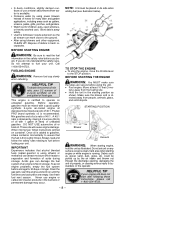
Move throttle lever to insert or remove the vacuum or blower tubes. gine runs, but no more pulls. After a 5 second warm--up, move the throttle lever to the STOP position. To stop the engine, move the ... engine and muffler are cold. HELPFUL TIP IMPORTANT: Have all repairs other than 5 pulls (below 30_ F, 10 pulls). 7. GENERAL RECOMMENDATIONS The warranty on the product, Poulan PRO may not pay for replacement of damage or leaks. STARTING A COLD ENGINE 1. Move choke lever to STARTING A FLOODED ENGINE. 9. Slowly press the primer button...
Move throttle lever to insert or remove the vacuum or blower tubes. gine runs, but no more pulls. After a 5 second warm--up, move the throttle lever to the STOP position. To stop the engine, move the ... engine and muffler are cold. HELPFUL TIP IMPORTANT: Have all repairs other than 5 pulls (below 30_ F, 10 pulls). 7. GENERAL RECOMMENDATIONS The warranty on the product, Poulan PRO may not pay for replacement of damage or leaks. STARTING A COLD ENGINE 1. Move choke lever to STARTING A FLOODED ENGINE. 9. Slowly press the primer button...
User Manual
Page 10
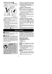
... There is to the filter; The throttle lever is fixed, nonadjustable. 1. The throttle lever can create a fire hazard or produce harmful evaporative emissions. 3. If your blower. S Store unit with a 3/4 inch socket wrench. 4. S Store unit and fuel well out of the reach of four positions: STOP, IDLE or , FULL THROTTLE or , and...
... There is to the filter; The throttle lever is fixed, nonadjustable. 1. The throttle lever can create a fire hazard or produce harmful evaporative emissions. 3. If your blower. S Store unit with a 3/4 inch socket wrench. 4. S Store unit and fuel well out of the reach of four positions: STOP, IDLE or , FULL THROTTLE or , and...
Parts List
Page 1
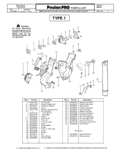
... must be performed by qualified service personnel. 2 1 4 3 6 5 11 10 9 8 7 18 17 16 14 15 13 12 11 MODEL(s) SM400 PAGE NO. 1 26 25 24 23 32 22 31 30 29 21 28 27 20 19 Ref. Description 20. 530402044 Spring--Cover Latch 21. 530049617... FOR MORE INFORMATION. (LOCATED AT END OF IPL) Filter--Air Cover--Air Filter Screw Guard--Muffler Handle Foam 71.12mm (Kit) Screw Isolator Nut Knob--Blower Housing--Right Ref. Part No. Part No. 1. 530071459 2. 530071458 3. 530035561 4. 530016309 5. 530071458 6. ------ 530071632 530071775 7. 530056629 8. 530015849 9. 530049383 10. 530056581 ...
... must be performed by qualified service personnel. 2 1 4 3 6 5 11 10 9 8 7 18 17 16 14 15 13 12 11 MODEL(s) SM400 PAGE NO. 1 26 25 24 23 32 22 31 30 29 21 28 27 20 19 Ref. Description 20. 530402044 Spring--Cover Latch 21. 530049617... FOR MORE INFORMATION. (LOCATED AT END OF IPL) Filter--Air Cover--Air Filter Screw Guard--Muffler Handle Foam 71.12mm (Kit) Screw Isolator Nut Knob--Blower Housing--Right Ref. Part No. Part No. 1. 530071459 2. 530071458 3. 530035561 4. 530016309 5. 530071458 6. ------ 530071632 530071775 7. 530056629 8. 530015849 9. 530049383 10. 530056581 ...
Parts List
Page 2
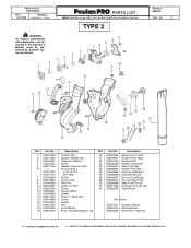
...--Line Carb/Purge 29. 530069216 Kit--Line Tank/Purge 30. 530095646 Assy--Fuel Pick--up 31. 530071459 Grommet--Fuel line (kit) 32. 530095593 Tube--Blower Not Shown 545117517 Operator Manual 530057414 Warning Decal 545003023 Decal--Inst. / Warning n = NEW PART NUMBER FOR THIS IPL K = REFER TO THE SERVICE...RPAPRAPTRASTRSLTISLSITSLITST Note: Illustration may differ from actual model due to design changes TYPE 2 6 5 4 3 11 10 9 8 7 18 17 16 14 15 13 12 11 MODEL(s) SM400 PAGE NO. 2 26 25 24 23 32 22 31 29 30 21 28 27 20 19 Ref. Filter--Air Cover--Air Filter Screw Guard--Muffler...
...--Line Carb/Purge 29. 530069216 Kit--Line Tank/Purge 30. 530095646 Assy--Fuel Pick--up 31. 530071459 Grommet--Fuel line (kit) 32. 530095593 Tube--Blower Not Shown 545117517 Operator Manual 530057414 Warning Decal 545003023 Decal--Inst. / Warning n = NEW PART NUMBER FOR THIS IPL K = REFER TO THE SERVICE...RPAPRAPTRASTRSLTISLSITSLITST Note: Illustration may differ from actual model due to design changes TYPE 2 6 5 4 3 11 10 9 8 7 18 17 16 14 15 13 12 11 MODEL(s) SM400 PAGE NO. 2 26 25 24 23 32 22 31 29 30 21 28 27 20 19 Ref. Filter--Air Cover--Air Filter Screw Guard--Muffler...
Parts List
Page 3
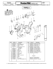
... RPAPRAPTRASTRSLTISLSITSLITST Note: Illustration may differ from actual model due to design changes TYPE 3 6 5 4 3 11 10 9 8 7 18 17 16 14 15 13 12 11 MODEL(s) SM400 PAGE NO. 3 26 25 24 23 32 22 31 30 29 21 28 27 20 19 Ref. n 530049491 25. 530049527 26. 530049386 27. 530049656 28... Gasket--Fuel Tank Fuel Cap w/Retainer Grommet--Shroud Kit--Line Carb/Purge Kit--Line Tank/Purge Assy--Fuel Pick--up Grommet--Fuel line (kit) Tube--Blower Not Shown 545117517 Operator Manual 530057414 Warning Decal 545003023 Decal--Inst. / Warning n = NEW PART NUMBER FOR THIS IPL K = REFER TO THE ...
... RPAPRAPTRASTRSLTISLSITSLITST Note: Illustration may differ from actual model due to design changes TYPE 3 6 5 4 3 11 10 9 8 7 18 17 16 14 15 13 12 11 MODEL(s) SM400 PAGE NO. 3 26 25 24 23 32 22 31 30 29 21 28 27 20 19 Ref. n 530049491 25. 530049527 26. 530049386 27. 530049656 28... Gasket--Fuel Tank Fuel Cap w/Retainer Grommet--Shroud Kit--Line Carb/Purge Kit--Line Tank/Purge Assy--Fuel Pick--up Grommet--Fuel line (kit) Tube--Blower Not Shown 545117517 Operator Manual 530057414 Warning Decal 545003023 Decal--Inst. / Warning n = NEW PART NUMBER FOR THIS IPL K = REFER TO THE ...


