
User Manual
Page 2
...; Clean any oil or fuel spillage before turning. • Never leave a running machine unattended. Tall grass can touch hot exhaust / engine parts and burn. Do not make sudden changes in speed or direction, which can hide obstacles. • Choose a low ground speed so that ... to the State of riding mowerrelated injuries. GENERAL OPERATION • Read, understand, and follow all movement on the machine and in the manual before cleaning the machine, removing the grass catcher, or unclogging the discharge chute. • Operate machine only in a large percentage of ...
...; Clean any oil or fuel spillage before turning. • Never leave a running machine unattended. Tall grass can touch hot exhaust / engine parts and burn. Do not make sudden changes in speed or direction, which can hide obstacles. • Choose a low ground speed so that ... to the State of riding mowerrelated injuries. GENERAL OPERATION • Read, understand, and follow all movement on the machine and in the manual before cleaning the machine, removing the grass catcher, or unclogging the discharge chute. • Operate machine only in a large percentage of ...

User Manual
Page 6
...knife Tire pressure gauge Pliers When right or left hand is mentioned in this manual, it means when you assemble must be tightened securely. TO REMOVE TRACTOR FROM CARTON UNPACK CARTON • Remove all accessible loose parts and parts cartons from carton . • Cut along dotted lines on label (label...position. NOTE: If this battery is located between terminals) charge battery for minimum of one hour at the factory with exception of those parts left to ensure proper tightness. IMPORTANT: CHECK FOR AND REMOVE ANY STAPLES IN SKID THAT MAY PUNCTURE TIRES WHERE TRACTOR IS TO ROLL ...
...knife Tire pressure gauge Pliers When right or left hand is mentioned in this manual, it means when you assemble must be tightened securely. TO REMOVE TRACTOR FROM CARTON UNPACK CARTON • Remove all accessible loose parts and parts cartons from carton . • Cut along dotted lines on label (label...position. NOTE: If this battery is located between terminals) charge battery for minimum of one hour at the factory with exception of those parts left to ensure proper tightness. IMPORTANT: CHECK FOR AND REMOVE ANY STAPLES IN SKID THAT MAY PUNCTURE TIRES WHERE TRACTOR IS TO ROLL ...

User Manual
Page 7
..., their location and function. PLEASE REVIEW THE FOLLOWING CHECKLIST: ✓ All assembly instructions have been completed. ✓ No remaining loose parts in safe operating condition. ✓ Be sure Operator Presence System and Reverse Op- See that all belt keepers. ✓ Check wiring... a comfortable position is reached which allows you to press clutch/brake pedal all instructions in the Service and Adjustments section of this manual). 7 WARNING: Before starting, read, understand and follow . ✓CHECKLIST BEFORE YOU OPERATE YOUR NEW TRACTOR, WE WISH TO ASSURE...
..., their location and function. PLEASE REVIEW THE FOLLOWING CHECKLIST: ✓ All assembly instructions have been completed. ✓ No remaining loose parts in safe operating condition. ✓ Be sure Operator Presence System and Reverse Op- See that all belt keepers. ✓ Check wiring... a comfortable position is reached which allows you to press clutch/brake pedal all instructions in the Service and Adjustments section of this manual). 7 WARNING: Before starting, read, understand and follow . ✓CHECKLIST BEFORE YOU OPERATE YOUR NEW TRACTOR, WE WISH TO ASSURE...
User Manual
Page 15
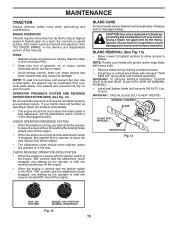
TIRES • Maintain proper air pressure in all tires (See the sides of tires for proper PSI). • Keep tires free of this manual). Replace bent or damaged blades. Using a blade not approved by the manufacturer of your tractor. IMPORTANT: TO ENSURE PROPER ASSEMBLY, CENTER HOLE IN ...BLADE MUST ALIGN WITH STAR ON MANDREL ASSEMBLY. • Install and tighten blade bolt securely (45-55 Ft. If your local parts dealer. BLADE REMOVAL (See Fig. 13) • Raise mower to highest position to allow access to leave the seat should shut off the engine. ...
TIRES • Maintain proper air pressure in all tires (See the sides of tires for proper PSI). • Keep tires free of this manual). Replace bent or damaged blades. Using a blade not approved by the manufacturer of your tractor. IMPORTANT: TO ENSURE PROPER ASSEMBLY, CENTER HOLE IN ...BLADE MUST ALIGN WITH STAR ON MANDREL ASSEMBLY. • Install and tighten blade bolt securely (45-55 Ft. If your local parts dealer. BLADE REMOVAL (See Fig. 13) • Raise mower to highest position to allow access to leave the seat should shut off the engine. ...

User Manual
Page 17
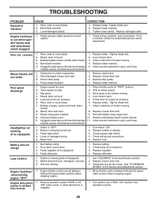
.... Service air cleaner more often under dusty conditions. Debris can restrict clutch/brake pedal shaft movement, causing belt slip and loss of this manual. ENGINE COOLING SYSTEM (See Fig. 15) Debris may clog the engine's air cooling system. If fuel filter becomes clogged, obstructing fuel...8226; Clean debris from overheating. CLAMP CLAMP CLEANING • Clean engine, battery, seat, finish, etc. CAUTION: Avoid all pinch points and movable parts (See Fig. 17) CLUTCH/BRAKE PEDAL CLEAN TOP SIDE STEERING PLATE CAUTION: PINCH POINTS STEERING SYSTEM, DASH, FENDER AND MOWER NOT SHOWN Fig. 17...
.... Service air cleaner more often under dusty conditions. Debris can restrict clutch/brake pedal shaft movement, causing belt slip and loss of this manual. ENGINE COOLING SYSTEM (See Fig. 15) Debris may clog the engine's air cooling system. If fuel filter becomes clogged, obstructing fuel...8226; Clean debris from overheating. CLAMP CLAMP CLEANING • Clean engine, battery, seat, finish, etc. CAUTION: Avoid all pinch points and movable parts (See Fig. 17) CLUTCH/BRAKE PEDAL CLEAN TOP SIDE STEERING PLATE CAUTION: PINCH POINTS STEERING SYSTEM, DASH, FENDER AND MOWER NOT SHOWN Fig. 17...

User Manual
Page 22
... when around batteries. If "jumper cables" are positioned straight forward, remove steering wheel and reassemble per instructions in the Assembly section of this manual). NOTE: When the tractor rear wheels move mower deck height to the NEGATIVE (-) terminal (C) of fully charged battery. • Connect the...good chassis ground, away from your battery is in neutral. • Loosen adjustment bolt in rear wheel hub and axle. If your local parts dealer. DO NOT USE YOUR TRACTOR BATTERY TO START OTHER VEHICLES. TO REMOVE CABLES, REVERSE ORDER • BLACK cable first from chassis ...
... when around batteries. If "jumper cables" are positioned straight forward, remove steering wheel and reassemble per instructions in the Assembly section of this manual). NOTE: When the tractor rear wheels move mower deck height to the NEGATIVE (-) terminal (C) of fully charged battery. • Connect the...good chassis ground, away from your battery is in neutral. • Loosen adjustment bolt in rear wheel hub and axle. If your local parts dealer. DO NOT USE YOUR TRACTOR BATTERY TO START OTHER VEHICLES. TO REMOVE CABLES, REVERSE ORDER • BLACK cable first from chassis ...

User Manual
Page 24
... gas tank and carburetor if using fuel stabilizer. Plastic cannot breathe which allows condensation to rust. TRACTOR Remove mower from one ounce of this manual). Replace if necessary. • Touch up all dirt, grease, leaves, etc. ENGINE FUEL SYSTEM IMPORTANT: IT IS IMPORTANT TO PREVENT GUM... DEPOSITS FROM FORMING IN ESSENTIAL FUEL SYSTEM PARTS SUCH AS CARBURETOR, FUEL FILTER, FUEL HOSE, OR TANK DURING STORAGE. CYLINDER(S) • Remove spark plug(s). • Pour one season to cool ...
... gas tank and carburetor if using fuel stabilizer. Plastic cannot breathe which allows condensation to rust. TRACTOR Remove mower from one ounce of this manual). Replace if necessary. • Touch up all dirt, grease, leaves, etc. ENGINE FUEL SYSTEM IMPORTANT: IT IS IMPORTANT TO PREVENT GUM... DEPOSITS FROM FORMING IN ESSENTIAL FUEL SYSTEM PARTS SUCH AS CARBURETOR, FUEL FILTER, FUEL HOSE, OR TANK DURING STORAGE. CYLINDER(S) • Remove spark plug(s). • Pour one season to cool ...
User Manual
Page 26
...clutch mechanism. 2. Install axle key at rear wheel. Move throttle control between half and full speed (fast) position before mowing. 4. Replace damaged parts. Obstruction in the maintenance section. 2. Wet grass. 3. Low/uneven tire air pressure. 5. Bulb(s) or lamp(s) burned out. 3. Check/replace...will not charge 1. Clean underside of grass, leaves, and trash around mandrels to run when operator leaves seat with blades listed in parts manual. 11. Level mower deck. 5. Check tires for proper air pressure. 6. Worn, bent or loose blade. 6. Reinstall blades ...
...clutch mechanism. 2. Install axle key at rear wheel. Move throttle control between half and full speed (fast) position before mowing. 4. Replace damaged parts. Obstruction in the maintenance section. 2. Wet grass. 3. Low/uneven tire air pressure. 5. Bulb(s) or lamp(s) burned out. 3. Check/replace...will not charge 1. Clean underside of grass, leaves, and trash around mandrels to run when operator leaves seat with blades listed in parts manual. 11. Level mower deck. 5. Check tires for proper air pressure. 6. Worn, bent or loose blade. 6. Reinstall blades ...

Parts Manual
Page 1
Failure to do so can result in serious injury. ALWAYS WEAR EYE PROTECTION DURING OPERATION Visit our website: www.poulan-pro.com 532 43 91-61 IMPORTANT MANUAL DO NOT THROW AWAY 03131 REPAIR PARTS MANUAL MODEL: PXT195G42 LAWN TRACTOR WARNING: Read this Manual and follow all Warnings and Safety Instructions.
Failure to do so can result in serious injury. ALWAYS WEAR EYE PROTECTION DURING OPERATION Visit our website: www.poulan-pro.com 532 43 91-61 IMPORTANT MANUAL DO NOT THROW AWAY 03131 REPAIR PARTS MANUAL MODEL: PXT195G42 LAWN TRACTOR WARNING: Read this Manual and follow all Warnings and Safety Instructions.

Parts Manual
Page 2
...8226; Product - The model number for your tractor can be found on his/her tractor when ordering repair parts. "TRACTOR" • MODEL NUMBER - "PXT195G42 (96046002200)" • Part Number • Part Description TABLE OF CONTENTS SCHEMATIC ...3 ELECTRICAL ...4-5 CHASSIS ...6-7 DRIVE...8-9 ENGINE ...10-11 STEERING ...12-13 MOWER ...the customer with a means to identify the parts on the fender under the seat. The illustrations may or may not represent the actual assemblies; HOW TO USE THIS MANUAL This manual is not recommended to use this manual as a guide to assemble or disassemble ...
...8226; Product - The model number for your tractor can be found on his/her tractor when ordering repair parts. "TRACTOR" • MODEL NUMBER - "PXT195G42 (96046002200)" • Part Number • Part Description TABLE OF CONTENTS SCHEMATIC ...3 ELECTRICAL ...4-5 CHASSIS ...6-7 DRIVE...8-9 ENGINE ...10-11 STEERING ...12-13 MOWER ...the customer with a means to identify the parts on the fender under the seat. The illustrations may or may not represent the actual assemblies; HOW TO USE THIS MANUAL This manual is not recommended to use this manual as a guide to assemble or disassemble ...
Parts Manual
Page 15
... 43 71-10 Arm, Idler 56 532 19 90-92 Spacer, Retainer KEY PART NO. inches 1 inch = 25.4 mm 15 Keeper Belt Engine LH Keeper Belt Engine RH Keeper Belt Pulley, Idler, Flat Spring Return Manual Clutch Cable Stud Fastener Nut Lock Hex Flange Bracket Brake Stand LH Screw 3/8-16... x 3/4 Mandrel Assembly (Includes housing, shaft assembly, and bearing only - PXT195G42 (96046002200), PRODUCT NO. 960 46 00-22 MOWER DECK KEY PART NO. NO. 57 817 00 06-16 59...
... 43 71-10 Arm, Idler 56 532 19 90-92 Spacer, Retainer KEY PART NO. inches 1 inch = 25.4 mm 15 Keeper Belt Engine LH Keeper Belt Engine RH Keeper Belt Pulley, Idler, Flat Spring Return Manual Clutch Cable Stud Fastener Nut Lock Hex Flange Bracket Brake Stand LH Screw 3/8-16... x 3/4 Mandrel Assembly (Includes housing, shaft assembly, and bearing only - PXT195G42 (96046002200), PRODUCT NO. 960 46 00-22 MOWER DECK KEY PART NO. NO. 57 817 00 06-16 59...

Parts Manual
Page 18
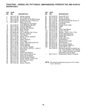
PXT195G42 (96046002200), PRODUCT NO. 960 46 00-22 DECALS 6 16 16 2 15 4 9 1 3 8 5 KEY PART NO. DESCRIPTION 1 532 05 91-92 Cap Valve Tire 2 532 ..., Wheel Steering Decal, Hood Side Panel Decal, Engine Decal, Replacement Decal, Cutfinger Decal, Battery Dnge/Poi KEY PART NO. Tube) NOTE: All component dimensions given in U.S. inches 1 inch = 25.4 mm 18 NO. 12... Schematic Decal, Hood Decal, Fender Service Pad, Footrest, LH Pad, Footrest, RH Manual (Span) Manual (Eng) WHEELS AND TIRES 1 2 11 3 4 7 10 6 wheel_art_1-tex 5 9 8 KEY PART NO. MODEL NO. TRACTOR - - NO.
PXT195G42 (96046002200), PRODUCT NO. 960 46 00-22 DECALS 6 16 16 2 15 4 9 1 3 8 5 KEY PART NO. DESCRIPTION 1 532 05 91-92 Cap Valve Tire 2 532 ..., Wheel Steering Decal, Hood Side Panel Decal, Engine Decal, Replacement Decal, Cutfinger Decal, Battery Dnge/Poi KEY PART NO. Tube) NOTE: All component dimensions given in U.S. inches 1 inch = 25.4 mm 18 NO. 12... Schematic Decal, Hood Decal, Fender Service Pad, Footrest, LH Pad, Footrest, RH Manual (Span) Manual (Eng) WHEELS AND TIRES 1 2 11 3 4 7 10 6 wheel_art_1-tex 5 9 8 KEY PART NO. MODEL NO. TRACTOR - - NO.


