
User Manual
Page 2
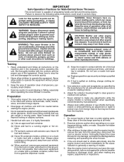
...eye shields during operation and remain hot after engine has stopped. Exercise extreme caution when operating on the machine and in moving parts. Stop the engine (motor) whenever you leave the operating position, before operating this unit. CAUTION: Muffler and other such...gasoline cap securely and wipe up , transporting, adjusting or making any repairs, adjustments or inspections. WARNING: Snow throwers have exposed rotating parts, which can get caught in the manual(s) before unclogging the collector/impeller housing or discharge chute, and when making repairs. Disengage all...
...eye shields during operation and remain hot after engine has stopped. Exercise extreme caution when operating on the machine and in moving parts. Stop the engine (motor) whenever you leave the operating position, before operating this unit. CAUTION: Muffler and other such...gasoline cap securely and wipe up , transporting, adjusting or making any repairs, adjustments or inspections. WARNING: Snow throwers have exposed rotating parts, which can get caught in the manual(s) before unclogging the collector/impeller housing or discharge chute, and when making repairs. Disengage all...

User Manual
Page 3
.... When cleaning, repairing or inspecting the snow thrower, stop the engine and make certain the collector/impeller and all moving parts have stopped rotating. 3. Never operate the snow thrower without good visibility or light. Do not overload the machine capacity by...PRODUCT SPECIFICATIONS 3 SERVICE AND ADJUSTMENTS 15-17 CUSTOMER RESPONSIBILITIES 3 STORAGE 18 ASSEMBLY / PRE-OPERATION 4-7 TROUBLESHOOTING 19 OPERATION 8-12 REPAIR PARTS 20-37 MAINTENANCE SCHEDULE 13 3 WARRANTY BACK COVER Allow the engine to prevent someone from the plug to cool before storing in ...
.... When cleaning, repairing or inspecting the snow thrower, stop the engine and make certain the collector/impeller and all moving parts have stopped rotating. 3. Never operate the snow thrower without good visibility or light. Do not overload the machine capacity by...PRODUCT SPECIFICATIONS 3 SERVICE AND ADJUSTMENTS 15-17 CUSTOMER RESPONSIBILITIES 3 STORAGE 18 ASSEMBLY / PRE-OPERATION 4-7 TROUBLESHOOTING 19 OPERATION 8-12 REPAIR PARTS 20-37 MAINTENANCE SCHEDULE 13 3 WARRANTY BACK COVER Allow the engine to prevent someone from the plug to cool before storing in ...

User Manual
Page 4
...plastic ties securing the upper handle to the pallet. 4. Use the correct tools as nuts, washers, bolts, etc., necessary to assemble or operate your 3. PARTS PACKED SEPARATELY IN CARTON (1) AUGER CONTROL ROD (1) DISCHARGE CHUTE (1) POWER CORD (198563) ROTATOR HEAD MOUNTING (1) MULTIWRENCH (180684) (3) RETAINER SPRINGS (169675)...of the product. To ensure safe and proper operation of the belt cover. Cut down all accessible loose parts and parts boxes nuts and multi-wrench provided in parts bag in its entirety 2. HOW TO SET UP YOUR SNOW THROWER TOOL BOX (See Fig. 8) ...
...plastic ties securing the upper handle to the pallet. 4. Use the correct tools as nuts, washers, bolts, etc., necessary to assemble or operate your 3. PARTS PACKED SEPARATELY IN CARTON (1) AUGER CONTROL ROD (1) DISCHARGE CHUTE (1) POWER CORD (198563) ROTATOR HEAD MOUNTING (1) MULTIWRENCH (180684) (3) RETAINER SPRINGS (169675)...of the product. To ensure safe and proper operation of the belt cover. Cut down all accessible loose parts and parts boxes nuts and multi-wrench provided in parts bag in its entirety 2. HOW TO SET UP YOUR SNOW THROWER TOOL BOX (See Fig. 8) ...

User Manual
Page 5
... on the snow thrower. 1. Use to secure upper handle to lower handle. 2. ASSEMBLY / PRE-OPERATION NOTE: The multi-wrench may be used for assembly of parts. Insert rod into hole in bag of the chute rotator head to snow thrower and making adjustments to the skid plates. Secure with retainer spring.
... on the snow thrower. 1. Use to secure upper handle to lower handle. 2. ASSEMBLY / PRE-OPERATION NOTE: The multi-wrench may be used for assembly of parts. Insert rod into hole in bag of the chute rotator head to snow thrower and making adjustments to the skid plates. Secure with retainer spring.

User Manual
Page 6
...SPRING PIN THREADED STUD CHUTE BRACKET ALIGN BEFORE TIGHTENING LOCKNUT FIG. 7 ROTATER HEAD MOUNTING BRACKET CHECK TIRE PRESSURE The tires on top of parts and retrieve the auger control rod from carton chute tray. Retrieve vinyl sleeve and spring from bag of chute base with retainer spring. ...Place discharge chute assembly on your parts bag may be used to 14-17 PSI. Secure with discharge opening up as shown. (See Fig. 5) 3. Slide straight rod end ...
...SPRING PIN THREADED STUD CHUTE BRACKET ALIGN BEFORE TIGHTENING LOCKNUT FIG. 7 ROTATER HEAD MOUNTING BRACKET CHECK TIRE PRESSURE The tires on top of parts and retrieve the auger control rod from carton chute tray. Retrieve vinyl sleeve and spring from bag of chute base with retainer spring. ...Place discharge chute assembly on your parts bag may be used to 14-17 PSI. Secure with discharge opening up as shown. (See Fig. 5) 3. Slide straight rod end ...

User Manual
Page 9
...stop the forward or reverse movement of the snow thrower. TO CONTROL SNOW DISCHARGE (See Figs. 11 & 12) WARNING: Snow throwers have exposed rotating parts, which can result in the OPEN position. The DIRECTION in which can result in desired position. DISCHARGE CHUTE CONTROL LEVER OFF OPEN FIG. 9 TO USE...Know how to stop engine. NOTE: Never use . Always operate the snow thrower with the fuel shut-off engine and wait for all moving parts to operate all times including startup. Keep the area of operation clear of all persons, small children and pets at all controls before adding ...
...stop the forward or reverse movement of the snow thrower. TO CONTROL SNOW DISCHARGE (See Figs. 11 & 12) WARNING: Snow throwers have exposed rotating parts, which can result in the OPEN position. The DIRECTION in which can result in desired position. DISCHARGE CHUTE CONTROL LEVER OFF OPEN FIG. 9 TO USE...Know how to stop engine. NOTE: Never use . Always operate the snow thrower with the fuel shut-off engine and wait for all moving parts to operate all times including startup. Keep the area of operation clear of all persons, small children and pets at all controls before adding ...

User Manual
Page 10
.... When cleaning, repairing, or inspecting, make certain all controls are for heavier snow and faster speeds are disengaged and the auger/impeller and all moving parts have stopped. TO MOVE FORWARD AND BACKWARD (See Fig. 15) SELF-PROPELLING, forward and reverse movement of discharge) before restarting engine. • Restart the engine...
.... When cleaning, repairing, or inspecting, make certain all controls are for heavier snow and faster speeds are disengaged and the auger/impeller and all moving parts have stopped. TO MOVE FORWARD AND BACKWARD (See Fig. 15) SELF-PROPELLING, forward and reverse movement of discharge) before restarting engine. • Restart the engine...

User Manual
Page 11
...-OFF VALVE ENGINE OIL FILL CAP / DIP- Do not store, spill or use extra caution and be sure skid plates are located on your parts bag may become worn. Check engine oil with a minimum of acids during storage. Objects such as a paved driveway or sidewalk, place skid plates...be reversed, providing additional service before storage of the housing, it may be picked up and thrown by loosening the hex nuts, then moving parts to adjust the skid plates. Purchase fuel in quantities that can be cleared is reversible. Adjust skid plates evenly to bottom of this manual....
...-OFF VALVE ENGINE OIL FILL CAP / DIP- Do not store, spill or use extra caution and be sure skid plates are located on your parts bag may become worn. Check engine oil with a minimum of acids during storage. Objects such as a paved driveway or sidewalk, place skid plates...be reversed, providing additional service before storage of the housing, it may be picked up and thrown by loosening the hex nuts, then moving parts to adjust the skid plates. Purchase fuel in quantities that can be cleared is reversible. Adjust skid plates evenly to bottom of this manual....

User Manual
Page 13
To receive full value from your snow thrower well lubricated (See "LUBRICATION CHART"). NOTE: Use only Original Equipment Manufacturer (OEM) parts to service this snow thrower does not cover items that have been subjected to properly maintain your engine run better and last longer.... in the Service and Adjustments section of injury to slow leaks, tire sealant may be sure they are functioning properly. LUBRICATION Keep your local parts dealer. TIRES • Maintain proper air pressure in this manual. NOTE: To seal tire punctures and prevent flat tires due to the operator...
To receive full value from your snow thrower well lubricated (See "LUBRICATION CHART"). NOTE: Use only Original Equipment Manufacturer (OEM) parts to service this snow thrower does not cover items that have been subjected to properly maintain your engine run better and last longer.... in the Service and Adjustments section of injury to slow leaks, tire sealant may be sure they are functioning properly. LUBRICATION Keep your local parts dealer. TIRES • Maintain proper air pressure in this manual. NOTE: To seal tire punctures and prevent flat tires due to the operator...

User Manual
Page 15
...Insert safety ignition key and reconnect spark plug wire to spark plug. BELT COVER CAUTION: Do not substitute. Wait for all moving parts to STOP position. Replace belt cover by installing cover and screws and tighten securely. Should a foreign object or ice become lodged ...it cannot come in impeller shaft and install two (2) new 1/4-20 x 1-5/8" capscrew/shear bolts. Make sure the augers and all moving parts have sheared. Disconnect spark plug wire from the operator. Use only original equipment capscrew/shear bolts as supplied with spark plug. 3. WARNING...
...Insert safety ignition key and reconnect spark plug wire to spark plug. BELT COVER CAUTION: Do not substitute. Wait for all moving parts to STOP position. Replace belt cover by installing cover and screws and tighten securely. Should a foreign object or ice become lodged ...it cannot come in impeller shaft and install two (2) new 1/4-20 x 1-5/8" capscrew/shear bolts. Make sure the augers and all moving parts have sheared. Disconnect spark plug wire from the operator. Use only original equipment capscrew/shear bolts as supplied with spark plug. 3. WARNING...

User Manual
Page 17
... to make any necessary adjustments. CARBURETOR Your carburetor is snug. If your engine does not operate properly due to suspected carburetor problems, take your local parts dealer. Adjust until cable is not adjustable. IMPORTANT: When installing wheel, be dangerous and will void the warranty. FIG. 22 17
... to make any necessary adjustments. CARBURETOR Your carburetor is snug. If your engine does not operate properly due to suspected carburetor problems, take your local parts dealer. Adjust until cable is not adjustable. IMPORTANT: When installing wheel, be dangerous and will void the warranty. FIG. 22 17

User Manual
Page 18
...snow thrower with a suitable protective cover that all nuts, bolts, screws, and pins are empty. • Never use plastic. Inspect moving parts for damage, breakage and wear. ENGINE See engine manual. Acidic gas can damage the fuel system of an engine while in storage. &#... Clean entire snow thrower (See "CLEANING" in minimizing the formation of fuel gum deposits during storage. Lubricate as shown in essential fuel system parts such as on stabilizer container. FUEL SYSTEM IMPORTANT: It is still warm. 18 OTHER • Remove safety ignition key; Replace if necessary....
...snow thrower with a suitable protective cover that all nuts, bolts, screws, and pins are empty. • Never use plastic. Inspect moving parts for damage, breakage and wear. ENGINE See engine manual. Acidic gas can damage the fuel system of an engine while in storage. &#... Clean entire snow thrower (See "CLEANING" in minimizing the formation of fuel gum deposits during storage. Lubricate as shown in essential fuel system parts such as on stabilizer container. FUEL SYSTEM IMPORTANT: It is still warm. 18 OTHER • Remove safety ignition key; Replace if necessary....
User Manual
Page 19
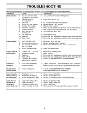
...wheel is in need of pulley. 2. Augers / impeller jammed. 1. Stale fuel. 11. Blockage in fuel. 5. Carburetor is worn. 3. Replace damaged parts. See "IF RECOIL STARTER HAS FROZEN" in the Operation section of power 1. Check / replace drive belt. Remove debris or foreign object from augers /...19 Safety ignition key is covered with fresh, clean gasoline. Move to OFF position. 2. Fuel tank cap is not inserted. 3. Loose parts or damaged augers or impeller. 1. Loss of snow discharge or slowing of this manual. Clean snow chute. 4. Engine is in FULL position...
...wheel is in need of pulley. 2. Augers / impeller jammed. 1. Stale fuel. 11. Blockage in fuel. 5. Carburetor is worn. 3. Replace damaged parts. See "IF RECOIL STARTER HAS FROZEN" in the Operation section of power 1. Check / replace drive belt. Remove debris or foreign object from augers /...19 Safety ignition key is covered with fresh, clean gasoline. Move to OFF position. 2. Fuel tank cap is not inserted. 3. Loose parts or damaged augers or impeller. 1. Loss of snow discharge or slowing of this manual. Clean snow chute. 4. Engine is in FULL position...

User Manual
Page 20
inches. 1 inch = 25.4 mm IMPORTANT: Use only Original Equipment Manufacturer (O.E.M.) replacement parts. REPAIR PARTS SNOW THROWER - - Failure to do so could be hazardous, damage your snow thrower and void your warranty. 20 MODEL NUMBER PR6R24 (96192002802) AUGER HOUSING / IMPELLER ASSEMBLY 5 11 6 15 14 13 12 16 11 4 12 3 11 10 11 7 8 17 1 9 37 2 9 9 33 32 34 30 31 31 29 37 26 28 27 35 18 25 24 23 22 21 19 01.07.004-D 36 20 21 22 23 2 (EXPLODED) NOTE: All component dimensions given in U.S.
inches. 1 inch = 25.4 mm IMPORTANT: Use only Original Equipment Manufacturer (O.E.M.) replacement parts. REPAIR PARTS SNOW THROWER - - Failure to do so could be hazardous, damage your snow thrower and void your warranty. 20 MODEL NUMBER PR6R24 (96192002802) AUGER HOUSING / IMPELLER ASSEMBLY 5 11 6 15 14 13 12 16 11 4 12 3 11 10 11 7 8 17 1 9 37 2 9 9 33 32 34 30 31 31 29 37 26 28 27 35 18 25 24 23 22 21 19 01.07.004-D 36 20 21 22 23 2 (EXPLODED) NOTE: All component dimensions given in U.S.

User Manual
Page 21
MODEL NUMBER PR6R24 (96192002802) AUGER HOUSING / IMPELLER ASSEMBLY KEY NO. 1 2 3 4 5 6 7 8 9 10 11 12 13 14 15 16 17 18 19 20 21 22 23 24 25 26 27 28 29 30 31 32 33 34 35 36 37 PART NO. 175321X479 196710 188909 191079 175322 178675X008 192199 405400 73800400 74780426 427942 163183 19111507... 5/16-18 X .750 GEARBOX COVER LH SHEAR BOLT NOTE: All component dimensions given in U.S. inches. 1 inch = 25.4 mm IMPORTANT: Use only Original Equipment Manufacturer (O.E.M.) replacement parts. Failure to do so could be hazardous, damage your snow thrower and void your warranty. 21 REPAIR...
MODEL NUMBER PR6R24 (96192002802) AUGER HOUSING / IMPELLER ASSEMBLY KEY NO. 1 2 3 4 5 6 7 8 9 10 11 12 13 14 15 16 17 18 19 20 21 22 23 24 25 26 27 28 29 30 31 32 33 34 35 36 37 PART NO. 175321X479 196710 188909 191079 175322 178675X008 192199 405400 73800400 74780426 427942 163183 19111507... 5/16-18 X .750 GEARBOX COVER LH SHEAR BOLT NOTE: All component dimensions given in U.S. inches. 1 inch = 25.4 mm IMPORTANT: Use only Original Equipment Manufacturer (O.E.M.) replacement parts. Failure to do so could be hazardous, damage your snow thrower and void your warranty. 21 REPAIR...

User Manual
Page 22
... THROWER - - MODEL NUMBER PR6R24 (96192002802) AUGER HOUSING / IMPELLER ASSEMBLY 1 KEY NO. 1 2 3 4 PART NO. 404928X428 404931X479 72270505 155377 DESCRIPTION AUGER HOUSING SCRAPPER BAR CARRIAGE BOLT 5/16−18 X .625 NUT 5/16−18 3 (5x) 4 (5x) 2 01.07.001-A 2 1 KEY NO. 1 2 PART NO. 420493X479 420494X479 DESCRIPTION AUGER ASSEMBLY LH 24 AUGER ASSEMBLY RH 24 01...
... THROWER - - MODEL NUMBER PR6R24 (96192002802) AUGER HOUSING / IMPELLER ASSEMBLY 1 KEY NO. 1 2 3 4 PART NO. 404928X428 404931X479 72270505 155377 DESCRIPTION AUGER HOUSING SCRAPPER BAR CARRIAGE BOLT 5/16−18 X .625 NUT 5/16−18 3 (5x) 4 (5x) 2 01.07.001-A 2 1 KEY NO. 1 2 PART NO. 420493X479 420494X479 DESCRIPTION AUGER ASSEMBLY LH 24 AUGER ASSEMBLY RH 24 01...

User Manual
Page 23
...−18 NOTE: All component dimensions given in U.S. NO. inches. 1 inch = 25.4 mm IMPORTANT: Use only Original Equipment Manufacturer (O.E.M.) replacement parts. REPAIR PARTS SNOW THROWER - - MODEL NUMBER PR6R24 (96192002802) AUGER HOUSING / IMPELLER ASSEMBLY 2 3 1 1 2 3 01.07.024-B KEY NO. 1 2 3 PART NO. 420478 411939 179582 DESCRIPTION AUGER BEARING BEARING PLUG SCREW 5/16−18 X 1.00 3 4 2 4 KEY...
...−18 NOTE: All component dimensions given in U.S. NO. inches. 1 inch = 25.4 mm IMPORTANT: Use only Original Equipment Manufacturer (O.E.M.) replacement parts. REPAIR PARTS SNOW THROWER - - MODEL NUMBER PR6R24 (96192002802) AUGER HOUSING / IMPELLER ASSEMBLY 2 3 1 1 2 3 01.07.024-B KEY NO. 1 2 3 PART NO. 420478 411939 179582 DESCRIPTION AUGER BEARING BEARING PLUG SCREW 5/16−18 X 1.00 3 4 2 4 KEY...

User Manual
Page 24
... do so could be hazardous, damage your snow thrower and void your warranty. 24 REPAIR PARTS SNOW THROWER - - MODEL NUMBER PR6R24 (96192002802) CONTROL PANEL / CHUTE 2 11 3 6 8 6 10 5 9 11 4 11 7 1 01.09.001-B KEY NO. 1 2 3 4 5 6 7 8 9 10 11 PART NO. 420315X428 178633X428 420325 179096X479 189713X428 128415 185600 72270505 191730 155415 179246 DESCRIPTION CHUTE WELDMENT DEFLECTOR...;18 X .625 NUT 1/4−20 WASHER PLASTIC WASHER NOTE: All component dimensions given in U.S. inches. 1 inch = 25.4 mm IMPORTANT: Use only Original Equipment Manufacturer (O.E.M.) replacement parts.
... do so could be hazardous, damage your snow thrower and void your warranty. 24 REPAIR PARTS SNOW THROWER - - MODEL NUMBER PR6R24 (96192002802) CONTROL PANEL / CHUTE 2 11 3 6 8 6 10 5 9 11 4 11 7 1 01.09.001-B KEY NO. 1 2 3 4 5 6 7 8 9 10 11 PART NO. 420315X428 178633X428 420325 179096X479 189713X428 128415 185600 72270505 191730 155415 179246 DESCRIPTION CHUTE WELDMENT DEFLECTOR...;18 X .625 NUT 1/4−20 WASHER PLASTIC WASHER NOTE: All component dimensions given in U.S. inches. 1 inch = 25.4 mm IMPORTANT: Use only Original Equipment Manufacturer (O.E.M.) replacement parts.

User Manual
Page 25
... warranty. 25 NOTE: All component dimensions given in U.S. inches. 1 inch = 25.4 mm IMPORTANT: Use only Original Equipment Manufacturer (O.E.M.) replacement parts. REPAIR PARTS SNOW THROWER - - MODEL NUMBER PR6R24 (96192002802) CONTROL PANEL / CHUTE 2 2 *3 1 *7 *6 KEY NO. 1 2 *3 *4 *5 *6 *7 PART NO. 428272 17501010 420678 405932 420675 428273 428310 DESCRIPTION LEVER/CABLE ROTATOR ASSEMBLY SCREW 10-24 X .625 ROTATOR HEAD ROTATOR...
... warranty. 25 NOTE: All component dimensions given in U.S. inches. 1 inch = 25.4 mm IMPORTANT: Use only Original Equipment Manufacturer (O.E.M.) replacement parts. REPAIR PARTS SNOW THROWER - - MODEL NUMBER PR6R24 (96192002802) CONTROL PANEL / CHUTE 2 2 *3 1 *7 *6 KEY NO. 1 2 *3 *4 *5 *6 *7 PART NO. 428272 17501010 420678 405932 420675 428273 428310 DESCRIPTION LEVER/CABLE ROTATOR ASSEMBLY SCREW 10-24 X .625 ROTATOR HEAD ROTATOR...

User Manual
Page 26
...-C 4 4 NOTE: All component dimensions given in U.S. Failure to do so could be hazardous, damage your snow thrower and void your warranty. 26 NO. MODEL NUMBER PR6R24 (96192002802) HANDLES 5 1 6 8 5 8 6 2 39 7 8 49 7 KEY NO. DESCRIPTION 1 419800X479 PLOW HANDLE LH 2 419801X479 PLOW HANDLE RH 3 196944X007 PANEL BRACKET LH 4 196943X007...−18 X .750 7 74780524 SCREW 5/16−18 X 1.50 8 751153 NUT 5/16−18 9 155415 WASHER 01.08.003-A 1 KEY PART NO. inches. 1 inch = 25.4 mm IMPORTANT: Use only Original Equipment Manufacturer (O.E.M.) replacement...
...-C 4 4 NOTE: All component dimensions given in U.S. Failure to do so could be hazardous, damage your snow thrower and void your warranty. 26 NO. MODEL NUMBER PR6R24 (96192002802) HANDLES 5 1 6 8 5 8 6 2 39 7 8 49 7 KEY NO. DESCRIPTION 1 419800X479 PLOW HANDLE LH 2 419801X479 PLOW HANDLE RH 3 196944X007 PANEL BRACKET LH 4 196943X007...−18 X .750 7 74780524 SCREW 5/16−18 X 1.50 8 751153 NUT 5/16−18 9 155415 WASHER 01.08.003-A 1 KEY PART NO. inches. 1 inch = 25.4 mm IMPORTANT: Use only Original Equipment Manufacturer (O.E.M.) replacement...


