
Owner Manual
Page 3
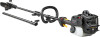
...01 HOUSING 20 530 01 57-68 NUT 21 530 05 65-28 ASSY OIL TANK PRUNER ATTACH 22 530 01 58-43 SCREW 23 530 09 59-10 ASSY TUBE LOWER DRIV 24 ...09 61-82 LINER CO EXTRUDED 25 530 09 62-18 SHAFT 26 530 05 55-03 TUBE CAP 587 70 51-01 ATTACHMENT PR28PS, 967089801, 2016-09 Remark QTY KIT NUT 1 CLAMP ASSY POLE PRUNER BAR BLACK 1 "SAW CHAIN 90P, 3/8"" mini ...ASSY GEAR PLUNGER 1 WASHER 1 ASSY OIL BLOCK 1 HOUSING POLE SAW UPPER BLACK 1 NUT 2 ASSY OIL TANK ATTACH PRUNER 1 SCREW 2 ASSY TUBE LOWER DRIV 1 LINER CO EXTRUDED 1 FLEX SHAFT LOWER 1 TUBE CAP 1 POLE SAW 1 1-22
...01 HOUSING 20 530 01 57-68 NUT 21 530 05 65-28 ASSY OIL TANK PRUNER ATTACH 22 530 01 58-43 SCREW 23 530 09 59-10 ASSY TUBE LOWER DRIV 24 ...09 61-82 LINER CO EXTRUDED 25 530 09 62-18 SHAFT 26 530 05 55-03 TUBE CAP 587 70 51-01 ATTACHMENT PR28PS, 967089801, 2016-09 Remark QTY KIT NUT 1 CLAMP ASSY POLE PRUNER BAR BLACK 1 "SAW CHAIN 90P, 3/8"" mini ...ASSY GEAR PLUNGER 1 WASHER 1 ASSY OIL BLOCK 1 HOUSING POLE SAW UPPER BLACK 1 NUT 2 ASSY OIL TANK ATTACH PRUNER 1 SCREW 2 ASSY TUBE LOWER DRIV 1 LINER CO EXTRUDED 1 FLEX SHAFT LOWER 1 TUBE CAP 1 POLE SAW 1 1-22

Instruction Manual
Page 2
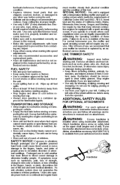
...! S You and others can be positioned only between the arrows. Always wear hearing protection, head protection, heavy, long pants, long sleeves, boots and gloves. This attachment is within the kickback danger zone. 2 Make sure no person is designed for thrown objects. IDENTIFICATION OF SAFETY SYMBOLS This unit can be blinded/injured...
...! S You and others can be positioned only between the arrows. Always wear hearing protection, head protection, heavy, long pants, long sleeves, boots and gloves. This attachment is within the kickback danger zone. 2 Make sure no person is designed for thrown objects. IDENTIFICATION OF SAFETY SYMBOLS This unit can be blinded/injured...

Instruction Manual
Page 3
...this product contains chemicals known to the State of California to cause cancer, birth defects or other optional attachment). Operator is designed for and repair 3 Read entire instruction manual before using gardening appliances, basic safety ... and spinning line (or other reproductive harm. Safety Requirements": Powerhead model Attachments PR28PS Trimmer head Type TNG 7 Cutting attachment / guard, part no. 537419221 / 530096106 952711828 Brushcutter attachment PP4000C SAFETY RULES (TRIMMER ATTACHMENT) When using unit! S Always wear hearing protection. A hot muffler...
...this product contains chemicals known to the State of California to cause cancer, birth defects or other optional attachment). Operator is designed for and repair 3 Read entire instruction manual before using gardening appliances, basic safety ... and spinning line (or other reproductive harm. Safety Requirements": Powerhead model Attachments PR28PS Trimmer head Type TNG 7 Cutting attachment / guard, part no. 537419221 / 530096106 952711828 Brushcutter attachment PP4000C SAFETY RULES (TRIMMER ATTACHMENT) When using unit! S Always wear hearing protection. A hot muffler...
Instruction Manual
Page 4
...to vibrations through prolonged use of California Codes 4442 and 4443. Stop engine immediately if you are approached. S Cut from your brushcutter attachment does not include a handlebar, a handlebar accessory kit (#530071451) is assembled correctly as numbness, pain, loss of strength, change in...Bystanders should be serviced or replaced by starting unit. S Use only for edging, pruning or hedge trimming. ADDITIONAL SAFETY RULES FOR OPTIONAL ATTACHMENTS S Allow engine to wear safety glasses. Handlebar 4 Mix and pour fuel outdoors. Avoid spilling fuel or oil. Keep in a ...
...to vibrations through prolonged use of California Codes 4442 and 4443. Stop engine immediately if you are approached. S Cut from your brushcutter attachment does not include a handlebar, a handlebar accessory kit (#530071451) is assembled correctly as numbness, pain, loss of strength, change in...Bystanders should be serviced or replaced by starting unit. S Use only for edging, pruning or hedge trimming. ADDITIONAL SAFETY RULES FOR OPTIONAL ATTACHMENTS S Allow engine to wear safety glasses. Handlebar 4 Mix and pour fuel outdoors. Avoid spilling fuel or oil. Keep in a ...
Instruction Manual
Page 5
... before attempting further operations. S Operate pruner only in daylight or good artificial light. S Do not use . S Only use from muffler and attachment. S Do not cut . S Make sure the chain will not make contact with the pruner. Never try to reduce the risk of your unit... below waist level. A hot muffler can be in good working condition. Do not overreach or use for damage. S Look for optional attachments). Look for and repair fuel leaks before performing maintenance except idle speed adjustments. Keep in good physical condition and mentally alert. S Make certain...
... before attempting further operations. S Operate pruner only in daylight or good artificial light. S Do not use . S Only use from muffler and attachment. S Do not cut . S Make sure the chain will not make contact with the pruner. Never try to reduce the risk of your unit... below waist level. A hot muffler can be in good working condition. Do not overreach or use for damage. S Look for optional attachments). Look for and repair fuel leaks before performing maintenance except idle speed adjustments. Keep in good physical condition and mentally alert. S Make certain...
Instruction Manual
Page 7
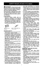
...damage in serious injury. S Reduced-Kickback Guide Bar, designed with a spark arresting screen. All U.S. ADDITIONAL SAFETY RULES FOR OPTIONAL ATTACHMENTS Large Radius Tip S Low-Kickback Chain, designed with a temperature limiting muffler and spark arresting screen which reduces the size of ...strength, change in skin color or texture, or loss of feeling in a direct line with your authorized service dealer. If your brushcutter attachment does not include a handlebar, a handlebar accessory kit (#530071451) is equipped with a contoured depth gauge and guard link which can ...
...damage in serious injury. S Reduced-Kickback Guide Bar, designed with a spark arresting screen. All U.S. ADDITIONAL SAFETY RULES FOR OPTIONAL ATTACHMENTS Large Radius Tip S Low-Kickback Chain, designed with a temperature limiting muffler and spark arresting screen which reduces the size of ...strength, change in skin color or texture, or loss of feeling in a direct line with your authorized service dealer. If your brushcutter attachment does not include a handlebar, a handlebar accessory kit (#530071451) is equipped with a contoured depth gauge and guard link which can ...
Instruction Manual
Page 8
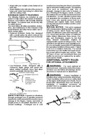
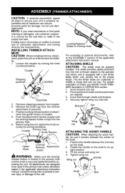
... you need assistance or find parts missing or damaged, call customer support. Insert bolt through shield and bracket. 4. Push the attachment into the primary hole. 6. Before using the unit, tighten the knob securely by turning the knob counterclockwise. Shaft Bolt 8...upright position. 3. dle, be sure it remains between the 2 arrows on a flat surface for stability. 1. INSTALLING TRIMMER ATTACHMENT CAUTION: When installing trimmer attach- The line limiter blade (on the shaft. 1. Loosen the coupler by turning clockwise. Position the handle between the arrows...
... you need assistance or find parts missing or damaged, call customer support. Insert bolt through shield and bracket. 4. Push the attachment into the primary hole. 6. Before using the unit, tighten the knob securely by turning the knob counterclockwise. Shaft Bolt 8...upright position. 3. dle, be sure it remains between the 2 arrows on a flat surface for stability. 1. INSTALLING TRIMMER ATTACHMENT CAUTION: When installing trimmer attach- The line limiter blade (on the shaft. 1. Loosen the coupler by turning clockwise. Position the handle between the arrows...

Instruction Manual
Page 9
...Loosen and remove both couplers and the knobs are secure. Place the upper shoulder strap clamp over the upper shaft. ASSEMBLY (PRUNER ATTACHMENT) CAUTION: If received assembled, repeat all fasteners are securely tightened before using the unit, tighten both knobs securely by the manufacturer...extension shaft with the engine completely stopped before operating the unit. NOTE: A one-half twist is normal for stability. Locking/ Release Attachment Button 6. WARNING: Make sure the locking/ release button is properly assembled and all steps to rest flat on engine end shaft....
...Loosen and remove both couplers and the knobs are secure. Place the upper shoulder strap clamp over the upper shaft. ASSEMBLY (PRUNER ATTACHMENT) CAUTION: If received assembled, repeat all fasteners are securely tightened before using the unit, tighten both knobs securely by the manufacturer...extension shaft with the engine completely stopped before operating the unit. NOTE: A one-half twist is normal for stability. Locking/ Release Attachment Button 6. WARNING: Make sure the locking/ release button is properly assembled and all steps to rest flat on engine end shaft....

Instruction Manual
Page 10
.... 4. Secure shoulder strap clamp by tightening screws with a hex wrench. Tighten wing nut. Upper Shoulder Strap Clamp POWERHEAD END ADJUSTING THE ASSIST HANDLE CAUTION: When attaching the assist handle, be sure it remains between the 2 arrows on the shaft to an upright position. 3. Shaft Bolt 10 3. Insert two screws into the... the lower shoulder strap clamp under the upper shaft and align the upper and lower clamp screw holes. Wing nut Handle Lower Shoulder Strap Clamp ATTACHMENT END Screws 4. Rotate the handle on the shaft. 2.
.... 4. Secure shoulder strap clamp by tightening screws with a hex wrench. Tighten wing nut. Upper Shoulder Strap Clamp POWERHEAD END ADJUSTING THE ASSIST HANDLE CAUTION: When attaching the assist handle, be sure it remains between the 2 arrows on the shaft to an upright position. 3. Shaft Bolt 10 3. Insert two screws into the... the lower shoulder strap clamp under the upper shaft and align the upper and lower clamp screw holes. Wing nut Handle Lower Shoulder Strap Clamp ATTACHMENT END Screws 4. Rotate the handle on the shaft. 2.

Instruction Manual
Page 11
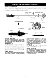
To stop engine. This allows you to start lever to the START position. START LEVER COUPLER 11 The COUPLER enables optional attachments to stop the engine, push and release the engine ON/STOP switch. KNOW YOUR TRIMMER ON/STOP switch Assist handle Coupler Shaft Primer bulb... fewer pulls on the unit. Activate the primer bulb by moving the start the engine with your unit to its original form. OPERATION (TRIMMER ATTACHMENT) READ THIS INSTRUCTION MANUAL AND SAFETY RULES BEFORE OPERATING YOUR UNIT. The PRIMER BULB removes air from the carburetor and fuel lines and fills them...
To stop engine. This allows you to start lever to the START position. START LEVER COUPLER 11 The COUPLER enables optional attachments to stop the engine, push and release the engine ON/STOP switch. KNOW YOUR TRIMMER ON/STOP switch Assist handle Coupler Shaft Primer bulb... fewer pulls on the unit. Activate the primer bulb by moving the start the engine with your unit to its original form. OPERATION (TRIMMER ATTACHMENT) READ THIS INSTRUCTION MANUAL AND SAFETY RULES BEFORE OPERATING YOUR UNIT. The PRIMER BULB removes air from the carburetor and fuel lines and fills them...

Instruction Manual
Page 13
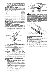
... line will be thrown into the primary hole. 4. OPERATING THE COUPLER This model is securely tightened before removing or installing attachments. All attachments are : MODEL: Edger ...PP1000E Cultivator ...PP2000T Blower ...PP3000B Brushcutter ...PP4000C Pruner ...PP5000P Pruner ...PP5500P Hedge Trimmer ...PP6000H...serious injury or damage to idle speed when not cutting. Loosen the coupler by turning clockwise. REMOVING TRIMMER ATTACHMENT (OR OTHER OPTIONAL ATTACHMENTS) CAUTION: When removing or installing at full throttle. Before using the unit, tighten the knob securely by ...
... line will be thrown into the primary hole. 4. OPERATING THE COUPLER This model is securely tightened before removing or installing attachments. All attachments are : MODEL: Edger ...PP1000E Cultivator ...PP2000T Blower ...PP3000B Brushcutter ...PP4000C Pruner ...PP5000P Pruner ...PP5500P Hedge Trimmer ...PP6000H...serious injury or damage to idle speed when not cutting. Loosen the coupler by turning clockwise. REMOVING TRIMMER ATTACHMENT (OR OTHER OPTIONAL ATTACHMENTS) CAUTION: When removing or installing at full throttle. Before using the unit, tighten the knob securely by ...
Instruction Manual
Page 15
The COUPLER enables optional attachments to start lever to stop the engine, push and release the engine ON/STOP switch. You should check your unit to its original form. The ... START LEVER 15 This allows you to be installed on the unit. Activate the starting . OPERATION (PRUNER ATTACHMENT) READ THIS INSTRUCTION MANUAL AND SAFETY RULES BEFORE OPERATING YOUR UNIT. Assist handle Pruner Shaft Attachment hanger Coupler ON/STOP switch KNOW YOUR PRUNER Shoulder strap clamp Primer bulb Throttle trigger Starter handle Bar...
The COUPLER enables optional attachments to start lever to stop the engine, push and release the engine ON/STOP switch. You should check your unit to its original form. The ... START LEVER 15 This allows you to be installed on the unit. Activate the starting . OPERATION (PRUNER ATTACHMENT) READ THIS INSTRUCTION MANUAL AND SAFETY RULES BEFORE OPERATING YOUR UNIT. Assist handle Pruner Shaft Attachment hanger Coupler ON/STOP switch KNOW YOUR PRUNER Shoulder strap clamp Primer bulb Throttle trigger Starter handle Bar...
Instruction Manual
Page 17
... be installed. Coupler Locking/Release Button in the primary hole and the knob is securely tightened before removing or installing attachments. Push hanger onto the attachment until the locking/release button snaps into the primary hole. 4. Repeat steps to remove extension shaft from coupler on...locking/release button. OPERATING THE COUPLER Pull starter rope handle until the locking/release button snaps into the hole. The optional attachments are designed to TROUBLESHOOTING TABLE or call customer support. Using the wrong hole could lead to serious injury or damage to be...
... be installed. Coupler Locking/Release Button in the primary hole and the knob is securely tightened before removing or installing attachments. Push hanger onto the attachment until the locking/release button snaps into the primary hole. 4. Repeat steps to remove extension shaft from coupler on...locking/release button. OPERATING THE COUPLER Pull starter rope handle until the locking/release button snaps into the hole. The optional attachments are designed to TROUBLESHOOTING TABLE or call customer support. Using the wrong hole could lead to serious injury or damage to be...

Instruction Manual
Page 18
... allow the engine to return to the unit may occur. Foot 2. DO NOT use back and forth sawing action. OPERATING INSTRUCTIONS OPERATING INSTRUCTIONS FOR PRUNER ATTACHMENT OPERATING POSITION ALWAYS WEAR: Head protection Eye protection Long pants Heavy shoes S Plan cut , accelerate to avoid tripping over them. Do not stand beneath branch...
... allow the engine to return to the unit may occur. Foot 2. DO NOT use back and forth sawing action. OPERATING INSTRUCTIONS OPERATING INSTRUCTIONS FOR PRUNER ATTACHMENT OPERATING POSITION ALWAYS WEAR: Head protection Eye protection Long pants Heavy shoes S Plan cut , accelerate to avoid tripping over them. Do not stand beneath branch...

Instruction Manual
Page 19
... ignition system complies with a clean dry cloth. CLEAN AIR FILTER A dirty air filter decreases engine performance and increases fuel consumption and harmful emissions. MAINTENANCE (TRIMMER ATTACHMENT) Disconnect the spark plug before attempting to restart unit to allow switch to ensure the engine starts easier and runs better. Tabs Air filter CHECK...
... ignition system complies with a clean dry cloth. CLEAN AIR FILTER A dirty air filter decreases engine performance and increases fuel consumption and harmful emissions. MAINTENANCE (TRIMMER ATTACHMENT) Disconnect the spark plug before attempting to restart unit to allow switch to ensure the engine starts easier and runs better. Tabs Air filter CHECK...
Instruction Manual
Page 20
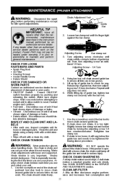
If any dealer other than an authorized service dealer performs work on the product, Poulan PRO may not pay for loose or damaged parts. Then, turn adjusting screw an additional 1/4 turn counterclockwise. S Oil tank - S Debris shield - INSPECT AND CLEAN ...even when it will sag below the guide bar and needs to be tightened following above procedure. If the pruner is very important. MAINTENANCE (PRUNER ATTACHMENT) WARNING: Disconnect the spark plug before attempting to restart unit to allow switch to reset. Ensure ON/STOP switch functions properly by turning the adjusting...
If any dealer other than an authorized service dealer performs work on the product, Poulan PRO may not pay for loose or damaged parts. Then, turn adjusting screw an additional 1/4 turn counterclockwise. S Oil tank - S Debris shield - INSPECT AND CLEAN ...even when it will sag below the guide bar and needs to be tightened following above procedure. If the pruner is very important. MAINTENANCE (PRUNER ATTACHMENT) WARNING: Disconnect the spark plug before attempting to restart unit to allow switch to reset. Ensure ON/STOP switch functions properly by turning the adjusting...

Instruction Manual
Page 22
... as shown. 22 9. Slot Tab Tab 7. Bend the line at the midpoint and insert the bend into position in a clockwise direction. SERVICE AND ADJUSTMENTS (TRIMMER ATTACHMENT) REPLACING THE LINE 1. Guide slot 2. Press the tabs on an existing spool, hold the spool as shown below.
... as shown. 22 9. Slot Tab Tab 7. Bend the line at the midpoint and insert the bend into position in a clockwise direction. SERVICE AND ADJUSTMENTS (TRIMMER ATTACHMENT) REPLACING THE LINE 1. Guide slot 2. Press the tabs on an existing spool, hold the spool as shown below.
Instruction Manual
Page 23
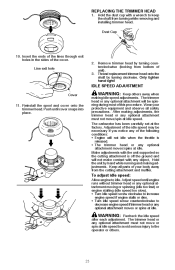
... increase engine speed if engine stalls or dies. To adjust idle speed: Allow engine to decrease engine speed if trimmer head or any optional attachment moves or spins at idle. Adjust speed until cover snaps into place. S Turn idle speed screw counterclockwise to idle. Dust Cup 10....Keep others . 23 Hold the unit by turning clockwise. WARNING: Recheck the idle speed after each adjustment. Hold the dust cup with any optional attachment must not move or spin at idle speed. The carburetor has been carefully set at idle. REPLACING THE TRIMMER HEAD 1. Line exit hole 2. ...
... increase engine speed if engine stalls or dies. To adjust idle speed: Allow engine to decrease engine speed if trimmer head or any optional attachment moves or spins at idle. Adjust speed until cover snaps into place. S Turn idle speed screw counterclockwise to idle. Dust Cup 10....Keep others . 23 Hold the unit by turning clockwise. WARNING: Recheck the idle speed after each adjustment. Hold the dust cup with any optional attachment must not move or spin at idle speed. The carburetor has been carefully set at idle. REPLACING THE TRIMMER HEAD 1. Line exit hole 2. ...

Instruction Manual
Page 25
... (90° ) so that dead or rotted wood will increase the chance of kickback which can result in size of cutter). SERVICE AND ADJUSTMENTS (PRUNER ATTACHMENT) Disconnect the spark plug before performing maintenance, service, or adjustments except for proper tension. Then, turn the chain saw around and repeat the process for...
... (90° ) so that dead or rotted wood will increase the chance of kickback which can result in size of cutter). SERVICE AND ADJUSTMENTS (PRUNER ATTACHMENT) Disconnect the spark plug before performing maintenance, service, or adjustments except for proper tension. Then, turn the chain saw around and repeat the process for...