Owner Manual
Page 14
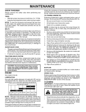
...NOTE: To seal tire punctures and prevent flat tires due to slow leaks, tire sealant may be purchased from snow thrower for draining oil). AUGER GEAR CASE • The gear case was filled with API service classification SG-SL. Keep oil at the beginning of a suitable container. ... where it could create a fire hazard and/or damage. WARNING: Remove safety ignition key and disconnect spark plug wire from spark plug. The belts are shown in the "PRODUCT SPECIFICATIONS" section of your engine oil level more freely when warm. • Catch oil in a suitable container....
...NOTE: To seal tire punctures and prevent flat tires due to slow leaks, tire sealant may be purchased from snow thrower for draining oil). AUGER GEAR CASE • The gear case was filled with API service classification SG-SL. Keep oil at the beginning of a suitable container. ... where it could create a fire hazard and/or damage. WARNING: Remove safety ignition key and disconnect spark plug wire from spark plug. The belts are shown in the "PRODUCT SPECIFICATIONS" section of your engine oil level more freely when warm. • Catch oil in a suitable container....
Owner Manual
Page 15
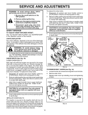
...spark plug wire to spark plug. 1/4-20 LOCKNUT 1/4-20 x 2 SHOULDER / SHEAR BOLT IMPELLER HUB IMPELLER SHAFT AUGER HUB 1/4-20 LOCKNUT AUGER HUB AUGER SHAFT FIG. 18 TO REMOVE BELT COVER (See Fig. 19) 1. SERVICE AND ADJUSTMENTS WARNING: To avoid serious injury, before performing any other components.... service or adjustments: 1. Place wire where it should be replaced. Loosen the two (2) screws securing belt cover to STOP position. If impeller does not turn when auger control lever is provided to STOP position. Wait for all controls and move throttle control to frame. ...
...spark plug wire to spark plug. 1/4-20 LOCKNUT 1/4-20 x 2 SHOULDER / SHEAR BOLT IMPELLER HUB IMPELLER SHAFT AUGER HUB 1/4-20 LOCKNUT AUGER HUB AUGER SHAFT FIG. 18 TO REMOVE BELT COVER (See Fig. 19) 1. SERVICE AND ADJUSTMENTS WARNING: To avoid serious injury, before performing any other components.... service or adjustments: 1. Place wire where it should be replaced. Loosen the two (2) screws securing belt cover to STOP position. If impeller does not turn when auger control lever is provided to STOP position. Wait for all controls and move throttle control to frame. ...

Owner Manual
Page 16
... the front and back sections. REMOVE GASOLINE FROM FUEL TANK - Wipe up . CHUTE ROTATOR HEAD LOCKNUT AUGER BELT REPLACEMENT (See Fig. 21) TO REMOVE AUGER BELT 1. Use a block under the snow thrower. Move auger belt tensioner arm and remove auger belt from under the hinge point to secure the snow thrower in the operating position and hold the...
... the front and back sections. REMOVE GASOLINE FROM FUEL TANK - Wipe up . CHUTE ROTATOR HEAD LOCKNUT AUGER BELT REPLACEMENT (See Fig. 21) TO REMOVE AUGER BELT 1. Use a block under the snow thrower. Move auger belt tensioner arm and remove auger belt from under the hinge point to secure the snow thrower in the operating position and hold the...

Owner Manual
Page 17
...department. Remove arm bolt and drive belt tensioner arm. 5. Install previously removed top bolt. Operate all controls to drive belt tensioner arm. 3. See "TO INSTALL AUGER BELT" in this section. 2. Remove auger belt. Remove pulley bolt, engine pulley, and drive belt from your snow thrower to slow... pulley groove properly before installing onto engine shaft. 4. Remove tensioner spring attached to ensure belts are installed properly and that all components are moving correctly. 9. Install auger belt. WHEEL PIN (INSTALL IN OUTER HOLE OF AXLE ONLY) RETAINER PIN OUTER HOLE AXLE ...
...department. Remove arm bolt and drive belt tensioner arm. 5. Install previously removed top bolt. Operate all controls to drive belt tensioner arm. 3. See "TO INSTALL AUGER BELT" in this section. 2. Remove auger belt. Remove pulley bolt, engine pulley, and drive belt from your snow thrower to slow... pulley groove properly before installing onto engine shaft. 4. Remove tensioner spring attached to ensure belts are installed properly and that all components are moving correctly. 9. Install auger belt. WHEEL PIN (INSTALL IN OUTER HOLE OF AXLE ONLY) RETAINER PIN OUTER HOLE AXLE ...
Owner Manual
Page 19
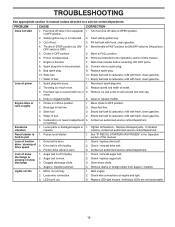
... Stale fuel. 10. Throwing too much snow. 2. Move choke to FULL position. 6. Tighten all fasteners. Auger belt is worn. 1. Check / replace auger belt. 3. LED burnt out. 3. Replace LED light module. (Individual LEDs are not replaceable) 19 TROUBLESHOOTING See ...traction drive / slowing of this manual. 7. Check / replace drive belt. 2. Check / reinstall drive belt. 3. Auger belt is 1. Check / reinstall auger belt. 2. Clean snow chute. 4. Augers / impeller jammed. 4. Lights not On 1. Start engine. 2. Loose wire connection. 2.
... Stale fuel. 10. Throwing too much snow. 2. Move choke to FULL position. 6. Tighten all fasteners. Auger belt is worn. 1. Check / replace auger belt. 3. LED burnt out. 3. Replace LED light module. (Individual LEDs are not replaceable) 19 TROUBLESHOOTING See ...traction drive / slowing of this manual. 7. Check / replace drive belt. 2. Check / reinstall drive belt. 3. Auger belt is 1. Check / reinstall auger belt. 2. Clean snow chute. 4. Augers / impeller jammed. 4. Lights not On 1. Start engine. 2. Loose wire connection. 2.
Owner Manual
Page 21
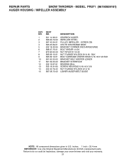
... LOWER BRACKET INTERFACE BEARING BALL SCREW HEX HEAD 5/16-18 X 5/8 NUT FLANGE NYLOCK 5/16-18 LOWER AUGER BELT GUIDE NOTE: All component dimensions given in U.S. MODEL PR271 (96192009101) AUGER HOUSING / IMPELLER ASSEMBLY KEY NO. 1 2 3 4 5 6 7 8 9 10 11 12 13 14 15 PART NO. 501 14 96-01 586 60 72-02 587 40 24-01... 63 20-02 581 59 25-02 532 19 87-91 532 16 31-83 532 42 79-42 587 58 72-02 DESCRIPTION GEARBOX AUGER IMPELLER STEEL PULLEY IMPELLER - SCREW ON CHUTE DISCHARGE BASE BRACKET CORNER DISCHARGE BASE BOLT SHEAR 1/4-20 NUT NYLOCK 1/4-20 NUT FLANGE NYLOCK 5/16-18...
... LOWER BRACKET INTERFACE BEARING BALL SCREW HEX HEAD 5/16-18 X 5/8 NUT FLANGE NYLOCK 5/16-18 LOWER AUGER BELT GUIDE NOTE: All component dimensions given in U.S. MODEL PR271 (96192009101) AUGER HOUSING / IMPELLER ASSEMBLY KEY NO. 1 2 3 4 5 6 7 8 9 10 11 12 13 14 15 PART NO. 501 14 96-01 586 60 72-02 587 40 24-01... 63 20-02 581 59 25-02 532 19 87-91 532 16 31-83 532 42 79-42 587 58 72-02 DESCRIPTION GEARBOX AUGER IMPELLER STEEL PULLEY IMPELLER - SCREW ON CHUTE DISCHARGE BASE BRACKET CORNER DISCHARGE BASE BOLT SHEAR 1/4-20 NUT NYLOCK 1/4-20 NUT FLANGE NYLOCK 5/16-18...

Owner Manual
Page 40
Failure to do so could be hazardous, damage your snow thrower and void your warranty. 40 DESCRIPTION 1 1 532 18 40-45 DECAL AUGER 4 2 532 19 96-82 DECAL CHUTE 3 532 19 96-83 DECAL AUGER SAFETY 4 532 18 40-28 DECAL BELT GUIDE 3 2 05.16.001-A NOTE: All component dimensions given in U.S. REPAIR PARTS DECALS SNOW THROWER - inches. 1 inch = 25.4 mm IMPORTANT: Use only Original Equipment Manufacturer (O.E.M.) replacement parts. NO. MODEL PR271 (96192009101) KEY PART NO.
Failure to do so could be hazardous, damage your snow thrower and void your warranty. 40 DESCRIPTION 1 1 532 18 40-45 DECAL AUGER 4 2 532 19 96-82 DECAL CHUTE 3 532 19 96-83 DECAL AUGER SAFETY 4 532 18 40-28 DECAL BELT GUIDE 3 2 05.16.001-A NOTE: All component dimensions given in U.S. REPAIR PARTS DECALS SNOW THROWER - inches. 1 inch = 25.4 mm IMPORTANT: Use only Original Equipment Manufacturer (O.E.M.) replacement parts. NO. MODEL PR271 (96192009101) KEY PART NO.

