
User Manual
Page 2
...free of -control and tipover accidents, which could be thrown. slope. 2 DO: • Mow up . I. Do not operate the mower without either the entire grass catcher or the guard in . If tires lose traction, disengage the blades and proceed slowly straight down before starting... or stopping on slopes unless necessary, and then, turn • Keep children out of riding mowerrelated injuries. The mower could overturn the machine. These operators should evaluate their proper Slopes are explosive. - SAFETY RULES Safe Operation Practices for wheel weights...
...free of -control and tipover accidents, which could be thrown. slope. 2 DO: • Mow up . I. Do not operate the mower without either the entire grass catcher or the guard in . If tires lose traction, disengage the blades and proceed slowly straight down before starting... or stopping on slopes unless necessary, and then, turn • Keep children out of riding mowerrelated injuries. The mower could overturn the machine. These operators should evaluate their proper Slopes are explosive. - SAFETY RULES Safe Operation Practices for wheel weights...

User Manual
Page 3
.... WARNING: Do not coast down slopes (15° Max), not across. • Remove obstacles such as rocks, tree limbs, etc. • Watch for Ride-On Mowers • Be sure the area is dangerous. Choose a low gear so that are recommended by and comply with the ground and cause you to stop...
.... WARNING: Do not coast down slopes (15° Max), not across. • Remove obstacles such as rocks, tree limbs, etc. • Watch for Ride-On Mowers • Be sure the area is dangerous. Choose a low gear so that are recommended by and comply with the ground and cause you to stop...

User Manual
Page 5
... Adapter Steering Wheel Insert (4) Washers 3/8 x 3/4 x 14 Ga. Seat (4) Retainer Springs (double loop) (4) Locknuts 3/8-16 Nose Roller (1) Washer 17/32 x 1-3/16 x 12 Gauge (1) Knob (2) Flanged Pins Mower (1) Front Plate Assembly (2) Locknuts 5/16-18 Rod Retainer Spring Nose Roller Brackets (2) Hex Bolts 5/16-18 x 1 (2) Retainer Springs (single loop) (5) Retainer Springs (double loop) Keys...
... Adapter Steering Wheel Insert (4) Washers 3/8 x 3/4 x 14 Ga. Seat (4) Retainer Springs (double loop) (4) Locknuts 3/8-16 Nose Roller (1) Washer 17/32 x 1-3/16 x 12 Gauge (1) Knob (2) Flanged Pins Mower (1) Front Plate Assembly (2) Locknuts 5/16-18 Rod Retainer Spring Nose Roller Brackets (2) Hex Bolts 5/16-18 x 1 (2) Retainer Springs (single loop) (5) Retainer Springs (double loop) Keys...
User Manual
Page 6
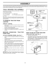
... (left unassembled for shipping purposes. To ensure safe and proper operation of your tractor all four corners of carton, and lay panels flat. • Remove mower and packing materials. • Check for any additional loose parts or cartons and remove. LABEL FIG. 2 6 TOOLS REQUIRED FOR ASSEMBLY A socket wrench set will make...
... (left unassembled for shipping purposes. To ensure safe and proper operation of your tractor all four corners of carton, and lay panels flat. • Remove mower and packing materials. • Check for any additional loose parts or cartons and remove. LABEL FIG. 2 6 TOOLS REQUIRED FOR ASSEMBLY A socket wrench set will make...
User Manual
Page 7
... set aside for assembly of seat to highest position and retain with clevis pins and spring retainers. • Adjust gauge wheels before operating mower. Continue with gasoline • Place freewheel control in "transmission engaged" position. • Sit on seat to disengage transmission (See "TO... area. Assemble gauge wheels as shown using shoulder bolts, 3/8 washers and 3/8-16 center locknuts and tighten securely. • For ease of mower to tractor assembly, raise gauge wheels to tractor. • Pivot seat upward and remove from the skid. Remove the cardboard packing and discard...
... set aside for assembly of seat to highest position and retain with clevis pins and spring retainers. • Adjust gauge wheels before operating mower. Continue with gasoline • Place freewheel control in "transmission engaged" position. • Sit on seat to disengage transmission (See "TO... area. Assemble gauge wheels as shown using shoulder bolts, 3/8 washers and 3/8-16 center locknuts and tighten securely. • For ease of mower to tractor assembly, raise gauge wheels to tractor. • Pivot seat upward and remove from the skid. Remove the cardboard packing and discard...

User Manual
Page 8
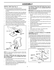
...tension rod is in pin is spring loaded. LOCK NUT HEX BOLT ROD TAB HOLE "B" BRACKET "A" BRACKET RETAINER SPRING NOSE ROLLER FIG. 5 INSTALL MOWER AND DRIVE BELT (See Figs. 6 and 7) Be sure tractor is on rod and engage slowly. •. Swing anti-sway bar to left side ...on outward pointing deck pins. Retain with double loop retainer spring with loops up as shown. • Position front plate assembly between plate and mower brackets. Secure pins with single loop retainer springs as shown. • Install front plate assembly to tractor suspension brackets and retain with double loop...
...tension rod is in pin is spring loaded. LOCK NUT HEX BOLT ROD TAB HOLE "B" BRACKET "A" BRACKET RETAINER SPRING NOSE ROLLER FIG. 5 INSTALL MOWER AND DRIVE BELT (See Figs. 6 and 7) Be sure tractor is on rod and engage slowly. •. Swing anti-sway bar to left side ...on outward pointing deck pins. Retain with double loop retainer spring with loops up as shown. • Position front plate assembly between plate and mower brackets. Secure pins with single loop retainer springs as shown. • Install front plate assembly to tractor suspension brackets and retain with double loop...
User Manual
Page 9
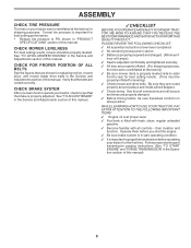
...: 3 All assembly instructions have been completed. 3 No remaining loose parts in drive position. See that are shown for leveling). 3 Check mower and drive belts. CHECK FOR PROPER POSITION OF ALL BELTS See the figures that all connections are still secure and wires are properly clamped. .... Be sure they are routed correctly. Operate them before operating your tractor, check to operate your tractor for shipping purposes. See "TO LEVEL MOWER HOUSING" in safe operating condition. 3 It is filled with fresh, clean, regular unleaded gasoline. 3 Become familiar with all belt keepers. 3...
...: 3 All assembly instructions have been completed. 3 No remaining loose parts in drive position. See that are shown for leveling). 3 Check mower and drive belts. CHECK FOR PROPER POSITION OF ALL BELTS See the figures that all connections are still secure and wires are properly clamped. .... Be sure they are routed correctly. Operate them before operating your tractor, check to operate your tractor for shipping purposes. See "TO LEVEL MOWER HOUSING" in safe operating condition. 3 It is filled with fresh, clean, regular unleaded gasoline. 3 Become familiar with all belt keepers. 3...

User Manual
Page 10
... ENGINE OFF LIGHTS ON P ENGINE ON ENGINE START PARKING BRAKE PARKING BRAKE PARKING BRAKE LOCKED UNLOCKED OVER TEMP LIGHT FUEL OIL PRESSURE BATTERY REVERSE FORWARD MOWER HEIGHT MOWER LIFT 15 15 15 ATTACHMENT ATTACHMENT CLUTCH ENGAGED CLUTCH DISENGAGED DANGER, KEEP HANDS AND FEET AWAY KEEP AREA CLEAR SLOPE HAZARDS (SEE SAFETY RULES...
... ENGINE OFF LIGHTS ON P ENGINE ON ENGINE START PARKING BRAKE PARKING BRAKE PARKING BRAKE LOCKED UNLOCKED OVER TEMP LIGHT FUEL OIL PRESSURE BATTERY REVERSE FORWARD MOWER HEIGHT MOWER LIFT 15 15 15 ATTACHMENT ATTACHMENT CLUTCH ENGAGED CLUTCH DISENGAGED DANGER, KEEP HANDS AND FEET AWAY KEEP AREA CLEAR SLOPE HAZARDS (SEE SAFETY RULES...

User Manual
Page 11
...YOUR TRACTOR Compare the illustrations with your tractor to familiarize yourself with the engine off. ATTACHMENT CLUTCH SWITCH: Used to engage the mower blades, or other attachments mounted to your tractor. CHOKE CONTROL: Used when starting and stopping the engine. HOURMETER - Used for... to release attachment lift lever when changing its position. Used to adjust the mower cutting height. BRAKE PEDAL - HEIGHT ADJUSTMENT KNOB - ATTACHMENT LIFT LEVER - Used to raise and lower the mower deck or other attachments mounted to control engine speed. CRUISE CONTROL LEVER - IGNITION...
...YOUR TRACTOR Compare the illustrations with your tractor to familiarize yourself with the engine off. ATTACHMENT CLUTCH SWITCH: Used to engage the mower blades, or other attachments mounted to your tractor. CHOKE CONTROL: Used when starting and stopping the engine. HOURMETER - Used for... to release attachment lift lever when changing its position. Used to adjust the mower cutting height. BRAKE PEDAL - HEIGHT ADJUSTMENT KNOB - ATTACHMENT LIFT LEVER - Used to raise and lower the mower deck or other attachments mounted to control engine speed. CRUISE CONTROL LEVER - IGNITION...

User Manual
Page 12
... height. TO MOVE FORWARD AND BACKWARD (See Fig. 8) "BRAKE" POSITION FORWARD PEDAL The direction and speed of grass being mowed. TO ADJUST MOWER CUTTING HEIGHT (See Fig. 8) The cutting height is controlled by turning the height adjustment knob in "BRAKE" position. The idle with the engine... stop tractor completely, as trimming at less than full throttle reduces the battery charging rate. • Full throttle offers the best bagging and mower perfor- IMPORTANT: LEAVING THE IGNITION SWITCH IN ANY POSITION OTHER THAN "OFF" WILL CAUSE THE BATTERY TO BE DISCHARGED, (DEAD). •...
... height. TO MOVE FORWARD AND BACKWARD (See Fig. 8) "BRAKE" POSITION FORWARD PEDAL The direction and speed of grass being mowed. TO ADJUST MOWER CUTTING HEIGHT (See Fig. 8) The cutting height is controlled by turning the height adjustment knob in "BRAKE" position. The idle with the engine... stop tractor completely, as trimming at less than full throttle reduces the battery charging rate. • Full throttle offers the best bagging and mower perfor- IMPORTANT: LEAVING THE IGNITION SWITCH IN ANY POSITION OTHER THAN "OFF" WILL CAUSE THE BATTERY TO BE DISCHARGED, (DEAD). •...

User Manual
Page 13
.... TO ADJUST GAUGE WHEELS (See Fig. 9) Gauge wheels are properly adjusted when they are in the Operation section of cut. • Lower mower with attachment lift control. • Pull freewheel control out and into clevis pin. • Be sure all turns slowly. the second to desired... CLUTCH SWITCH PUSH IN TO "DISENGAGED" DEFLECTOR SHIELD FIG. 10 TO OPERATE ON HILLS LOW POSITION RETAINER SPRING CLEVIS PIN FIG. 9 TO OPERATE MOWER (See Fig. 10) Your tractor is closed and secured to ground. OPERATION • The average lawn should be cut to approximately 2-1/2 inches ...
.... TO ADJUST GAUGE WHEELS (See Fig. 9) Gauge wheels are properly adjusted when they are in the Operation section of cut. • Lower mower with attachment lift control. • Pull freewheel control out and into clevis pin. • Be sure all turns slowly. the second to desired... CLUTCH SWITCH PUSH IN TO "DISENGAGED" DEFLECTOR SHIELD FIG. 10 TO OPERATE ON HILLS LOW POSITION RETAINER SPRING CLEVIS PIN FIG. 9 TO OPERATE MOWER (See Fig. 10) Your tractor is closed and secured to ground. OPERATION • The average lawn should be cut to approximately 2-1/2 inches ...
User Manual
Page 15
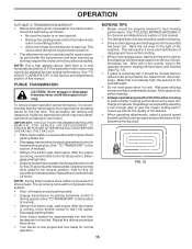
...to full forward position, hold for five feet. After the engine is running, move throttle control to the right so that clippings will plug mower and leave undesirable clumps. This will result in a more even distribution of clippings and more uniform cutting. • When mowing large areas,...control in driving position (See "TO TRANSPORT" in the Service and Adjustments section of this section of your tractor. See "TO LEVEL MOWER HOUSING" in this procedure there will remove any trapped air inside the transmission which may have developed during the engine warmup period after the...
...to full forward position, hold for five feet. After the engine is running, move throttle control to the right so that clippings will plug mower and leave undesirable clumps. This will result in a more even distribution of clippings and more uniform cutting. • When mowing large areas,...control in driving position (See "TO TRANSPORT" in the Service and Adjustments section of this section of your tractor. See "TO LEVEL MOWER HOUSING" in this procedure there will remove any trapped air inside the transmission which may have developed during the engine warmup period after the...

User Manual
Page 16
.... • Check brake operation. • Check tire pressure. • Check operator presence and interlock systems for proper operation. • Check for Loose Fasteners A Sharpen/Replace Mower Blades C T Lubrication Chart 0 Check Battery Level R Clean Battery and Terminals Check Transaxle Cooling Check V-Belts BEFOREEEVAECRHYU8ESVHEEORUYRS2E5VHEROYUR5E0SVEHROYUR1E0SV0EHROYUBSREESFAOSROENSSTEORRAVGEICE DATES 5 3 4 Check Engine Oil Level Change Engine Oil (with...
.... • Check brake operation. • Check tire pressure. • Check operator presence and interlock systems for proper operation. • Check for Loose Fasteners A Sharpen/Replace Mower Blades C T Lubrication Chart 0 Check Battery Level R Clean Battery and Terminals Check Transaxle Cooling Check V-Belts BEFOREEEVAECRHYU8ESVHEEORUYRS2E5VHEROYUR5E0SVEHROYUR1E0SV0EHROYUBSREESFAOSROENSSTEORRAVGEICE DATES 5 3 4 Check Engine Oil Level Change Engine Oil (with...

User Manual
Page 17
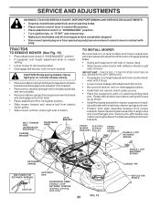
... rules when performing any attempt by the operator to blades. If your local parts dealer. BLADE REMOVAL (See Fig. 13) • Raise mower to highest position to allow access to leave the seat should shut off the engine. • The attachment clutch should shut off the engine.... also prevents tire dry rot and corrosion. OPERATOR PRESENCE SYSTEM Be sure operator presence and interlock systems are not. • Slide blade on the mower. • To check blade balance, you do not recommend sharpening blade - NOTE: Protect your tractor is in all tires (See "PRODUCT SPECIFICATIONS...
... rules when performing any attempt by the operator to blades. If your local parts dealer. BLADE REMOVAL (See Fig. 13) • Raise mower to highest position to allow access to leave the seat should shut off the engine. • The attachment clutch should shut off the engine.... also prevents tire dry rot and corrosion. OPERATOR PRESENCE SYSTEM Be sure operator presence and interlock systems are not. • Slide blade on the mower. • To check blade balance, you do not recommend sharpening blade - NOTE: Protect your tractor is in all tires (See "PRODUCT SPECIFICATIONS...
User Manual
Page 20
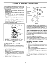
... as shown. • Install front plate assembly to tractor suspension brackets and retain with double loop retainer springs between front mower brackets. TRACTOR TO REMOVE MOWER (See Fig. 19) • Place attachment clutch in "DISENGAGED" position. • If equipped, turn height adjustment ...knob counterclockwise until it cannot come in contact with attachment lift control. FRONT ELECTRIC MOWER CLUTCH BRACKET PULLEY FRONT PLATE ASSEMBLY DOUBLE LOOP RETAINER SPRING RETAINER SPRING USE PLIERS FOR RETAINER SPRINGS LOOP UP ANTI-SWAY BAR ...
... as shown. • Install front plate assembly to tractor suspension brackets and retain with double loop retainer springs between front mower brackets. TRACTOR TO REMOVE MOWER (See Fig. 19) • Place attachment clutch in "DISENGAGED" position. • If equipped, turn height adjustment ...knob counterclockwise until it cannot come in contact with attachment lift control. FRONT ELECTRIC MOWER CLUTCH BRACKET PULLEY FRONT PLATE ASSEMBLY DOUBLE LOOP RETAINER SPRING RETAINER SPRING USE PLIERS FOR RETAINER SPRINGS LOOP UP ANTI-SWAY BAR ...

User Manual
Page 21
...loosen nut "C" on head of pin. CAUTION: Belt tension rod is pointing straight forward. Measure distance "B" at front than the rear tip when the mower is in its highest position. • Measure height from trunnion on both front links. • Recheck side-to 1/2" lower at front and rear tip...by approximately 3/16". • When distance "B" is 1/8" to -side adjustment. Make sure tires are not equal in length, adjust one side of mower, loosen lift link adjustment nut on right side of tractor. SERVICE AND ADJUSTMENTS NOTE: To assist in locating hole in flanged pin, the hole in...
...loosen nut "C" on head of pin. CAUTION: Belt tension rod is pointing straight forward. Measure distance "B" at front than the rear tip when the mower is in its highest position. • Measure height from trunnion on both front links. • Recheck side-to 1/2" lower at front and rear tip...by approximately 3/16". • When distance "B" is 1/8" to -side adjustment. Make sure tires are not equal in length, adjust one side of mower, loosen lift link adjustment nut on right side of tractor. SERVICE AND ADJUSTMENTS NOTE: To assist in locating hole in flanged pin, the hole in...

User Manual
Page 22
...equipped with retainer spring. • Reassemble R.H. mandrel pulley. • Remove belt from lock bracket. SERVICE AND ADJUSTMENTS TO REPLACE MOWER DRIVE BELT MOWER DRIVE BELT REMOVAL (See Fig. 24) • Park tractor on a level, dry concrete or paved surface, depress clutch/...brake pedal all grooves properly. • Reinstall L.H. Engage parking brake. • Lower mower to primary idler arm and spring arm. mandrel pulley carefully. • Remove belt from electric clutch pulley. • Remove belt from L.H....
...equipped with retainer spring. • Reassemble R.H. mandrel pulley. • Remove belt from lock bracket. SERVICE AND ADJUSTMENTS TO REPLACE MOWER DRIVE BELT MOWER DRIVE BELT REMOVAL (See Fig. 24) • Park tractor on a level, dry concrete or paved surface, depress clutch/...brake pedal all grooves properly. • Reinstall L.H. Engage parking brake. • Lower mower to primary idler arm and spring arm. mandrel pulley carefully. • Remove belt from electric clutch pulley. • Remove belt from L.H....
User Manual
Page 23
... is a belt installation guide decal on level surface. TO ADJUST STEERING WHEEL ALIGNMENT If steering wheel crossbars are not horizontal (left footrest. • Remove mower (See "TO REMOVE MOWER" in this section of this manual.) • Disconnect clutch wire harness. • Remove clutch locator. • Remove belt from around electric clutch. •...
... is a belt installation guide decal on level surface. TO ADJUST STEERING WHEEL ALIGNMENT If steering wheel crossbars are not horizontal (left footrest. • Remove mower (See "TO REMOVE MOWER" in this section of this manual.) • Disconnect clutch wire harness. • Remove clutch locator. • Remove belt from around electric clutch. •...
User Manual
Page 26
When mower is removed from dust and dirt. • Cover your tractor with a suitable protective cover that all rusted or chipped paint surfaces; Store in a clean, dry ... the stabilizer to reach the carburetor. WARNING: Never store the tractor with new spark plug(s). Inspect moving parts for damage, breakage and wear. TRACTOR Remove mower from one ounce of this manual).
When mower is removed from dust and dirt. • Cover your tractor with a suitable protective cover that all rusted or chipped paint surfaces; Store in a clean, dry ... the stabilizer to reach the carburetor. WARNING: Never store the tractor with new spark plug(s). Inspect moving parts for damage, breakage and wear. TRACTOR Remove mower from one ounce of this manual).

User Manual
Page 27
.... 4. Blown fuse. 5. Faulty solenoid or starter. 9. Check/replace ignition switch. 8. Faulty solenoid or starter. 1. Build-up of mower housing. 4. Dirty fuel filter. 8. Adjust throttle control. 3. Clean underside of grass, leaves and trash under mower. 4. Clean/replace air filter. 5. See "To Adjust Carburetor" in Operation section. 3. Replace damaged parts. 27 Corroded battery terminals...
.... 4. Blown fuse. 5. Faulty solenoid or starter. 9. Check/replace ignition switch. 8. Faulty solenoid or starter. 1. Build-up of mower housing. 4. Dirty fuel filter. 8. Adjust throttle control. 3. Clean underside of grass, leaves and trash under mower. 4. Clean/replace air filter. 5. See "To Adjust Carburetor" in Operation section. 3. Replace damaged parts. 27 Corroded battery terminals...


