
User Manual
Page 2
...8226; Do not overload the machine capacity by the manufacturer of instructions. It means CAUTION!!! Never allow bystanders near or under rotating parts. • Exercise extreme caution when operating on slippery surfaces. • Handle fuel with electric drive motors or electric starting when setting... (motor). • Do not operate the equipment without proper instruction. • Keep the area of operation clear of all moving parts have stopped. Be thoroughly familiar with the controls and the proper use care when backing. • Never allow adults to vibrate abnormally...
...8226; Do not overload the machine capacity by the manufacturer of instructions. It means CAUTION!!! Never allow bystanders near or under rotating parts. • Exercise extreme caution when operating on slippery surfaces. • Handle fuel with electric drive motors or electric starting when setting... (motor). • Do not operate the equipment without proper instruction. • Keep the area of operation clear of all moving parts have stopped. Be thoroughly familiar with the controls and the proper use care when backing. • Never allow adults to vibrate abnormally...
User Manual
Page 3
... OF CONTENTS SAFETY RULES 2 PRODUCT SPECIFICATIONS 3 CUSTOMER RESPONSIBILITIES 3 ASSEMBLY 4-5 OPERATION 6-9 MAINTENANCE SCHEDULE 10 MAINTENANCE 10-12 SERVICE & ADJUSTMENTS 12-14 STORAGE 15 TROUBLESHOOTING 16 REPAIR PARTS 17WARRANTY 17 3 Should you experience any problems you the best possible dependability and performance. IMPORTANT: THIS UNIT IS EQUIPPED WITH AN INTERNAL COMBUSTION ENGINE AND...
... OF CONTENTS SAFETY RULES 2 PRODUCT SPECIFICATIONS 3 CUSTOMER RESPONSIBILITIES 3 ASSEMBLY 4-5 OPERATION 6-9 MAINTENANCE SCHEDULE 10 MAINTENANCE 10-12 SERVICE & ADJUSTMENTS 12-14 STORAGE 15 TROUBLESHOOTING 16 REPAIR PARTS 17WARRANTY 17 3 Should you experience any problems you the best possible dependability and performance. IMPORTANT: THIS UNIT IS EQUIPPED WITH AN INTERNAL COMBUSTION ENGINE AND...
User Manual
Page 4
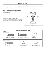
... 5/16-18 x 1-1/4 (6) Hex Nuts 5/16-18 (6) Lock Washers 5/16 4 ASSEMBLY Your new tiller has been assembled at the factory with exception of your tiller all parts and hardware you are listed. (1) Utility knife (1) Screwdriver (2) 1/2" wrenches OPERATOR'S POSITION (See Fig. 1) When right or left unassembled for shipping purposes. Use the correct... tools as necessary to insure proper tightness. To ensure safe and proper operation of those parts left hand is mentioned in the operating position (standing behind tiller handles).
... 5/16-18 x 1-1/4 (6) Hex Nuts 5/16-18 (6) Lock Washers 5/16 4 ASSEMBLY Your new tiller has been assembled at the factory with exception of your tiller all parts and hardware you are listed. (1) Utility knife (1) Screwdriver (2) 1/2" wrenches OPERATOR'S POSITION (See Fig. 1) When right or left unassembled for shipping purposes. Use the correct... tools as necessary to insure proper tightness. To ensure safe and proper operation of those parts left hand is mentioned in the operating position (standing behind tiller handles).
User Manual
Page 15
...section of fuel gum deposits during storage. ENGINE FUEL SYSTEM IMPORTANT: IT IS IMPORTANT TO PREVENT GUM DEPOSITS FROM FORMING IN ESSENTIAL FUEL SYSTEM PARTS SUCH AS THE CARBURETOR, FUEL FILTER, FUEL HOSE, OR TANK DURING STORAGE. Do not use engine or carburetor cleaner products in the ...STORAGE Immediately prepare your tiller for storage at least 10 minutes after adding stablizer to allow the stabilizer to reach the carburetor. Inspect moving parts for damage, breakage and wear. IMPORTANT: NEVER COVER TILLER WHILE ENGINE AND EXHAUST AREAS ARE STILL WARM. 15 NOTE: Fuel stablizer is ...
...section of fuel gum deposits during storage. ENGINE FUEL SYSTEM IMPORTANT: IT IS IMPORTANT TO PREVENT GUM DEPOSITS FROM FORMING IN ESSENTIAL FUEL SYSTEM PARTS SUCH AS THE CARBURETOR, FUEL FILTER, FUEL HOSE, OR TANK DURING STORAGE. Do not use engine or carburetor cleaner products in the ...STORAGE Immediately prepare your tiller for storage at least 10 minutes after adding stablizer to allow the stabilizer to reach the carburetor. Inspect moving parts for damage, breakage and wear. IMPORTANT: NEVER COVER TILLER WHILE ENGINE AND EXHAUST AREAS ARE STILL WARM. 15 NOTE: Fuel stablizer is ...

User Manual
Page 17
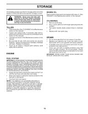
... 12 898 00 01-29 Nut, Flanged 5/16-18 13 532 18 08-47 Bolt, Carriage 5/16-18 x 3/4 Gr. 5 KEY PART NO. REPAIR PARTS TILLER - - inches. 1 inch = 25.4 mm 17 NO. MODEL NUMBER PPFT55 (96081000700) HANDLE ASSEMBLY 3 1 16 2 3 4 5 6 10 28 11 14 44 7 8 9 19 21 29 18 20 43 12 13 handle_assy_34 KEY...
... 12 898 00 01-29 Nut, Flanged 5/16-18 13 532 18 08-47 Bolt, Carriage 5/16-18 x 3/4 Gr. 5 KEY PART NO. REPAIR PARTS TILLER - - inches. 1 inch = 25.4 mm 17 NO. MODEL NUMBER PPFT55 (96081000700) HANDLE ASSEMBLY 3 1 16 2 3 4 5 6 10 28 11 14 44 7 8 9 19 21 29 18 20 43 12 13 handle_assy_34 KEY...

User Manual
Page 18
... 18 MODEL NUMBER PPFT55 (96081000700) BELT GUARD AND PULLEY ASSEMBLY 41 1 2 3 4 17 5 42 67 8 30 31 29 11 9 11 27 28 10 29 11 12 11 12 13 14 15 19 26 25 20 24 23 22 21 belt_guard_14 KEY PART NO. Cutting ...00 26-49 Key, Square 18 532 15 12-36 Pulley, Flat, Trans. 16 32 18 KEY PART NO. DESCRIPTION 19 532 18 85-02 Bolt, Belt Guard 20 812 00 00-36 Ring, Klip .... 41 532 18 03-07 Spring 42 532 13 89-09 Spacer NOTE: All component dimensions given in U.S. NO. REPAIR PARTS TILLER - - DESCRIPTION 1 532 18 03-77 Assembly, Bracket, Belt Guard 2 532 00 94-84 Clip, Cable 3...
... 18 MODEL NUMBER PPFT55 (96081000700) BELT GUARD AND PULLEY ASSEMBLY 41 1 2 3 4 17 5 42 67 8 30 31 29 11 9 11 27 28 10 29 11 12 11 12 13 14 15 19 26 25 20 24 23 22 21 belt_guard_14 KEY PART NO. Cutting ...00 26-49 Key, Square 18 532 15 12-36 Pulley, Flat, Trans. 16 32 18 KEY PART NO. DESCRIPTION 19 532 18 85-02 Bolt, Belt Guard 20 812 00 00-36 Ring, Klip .... 41 532 18 03-07 Spring 42 532 13 89-09 Spacer NOTE: All component dimensions given in U.S. NO. REPAIR PARTS TILLER - - DESCRIPTION 1 532 18 03-77 Assembly, Bracket, Belt Guard 2 532 00 94-84 Clip, Cable 3...

User Manual
Page 19
KEY PART NO. inches. 1 inch = 25.4 mm 19 NO. DESCRIPTION 15 532 12 47-24 Spring, Stake 16 532 12...00 Locknut, w/insert 5/16-18 24 873 97 05-00 Nut Lock Hex Flange NOTE: All component dimensions given in U.S. NO. MODEL NUMBER PPFT55 (96081000700) WHEEL AND DEPTH STAKE ASSEMBLY 1 23 7 9 6 8 13 10 2 16 21 20 24 18 17 19 18 20 19 ...wheel_d.stake_2 17 16 11 22 3 15 24 54 7 5 4 KEY PART NO. DESCRIPTION 1 532 00 91-94 Pin, Clevis 2 874 76 05-20 Bolt, Hex 5/16-18 x 1-1/4 3 874 76 05-12 Bolt, Hex 5/16-...
KEY PART NO. inches. 1 inch = 25.4 mm 19 NO. DESCRIPTION 15 532 12 47-24 Spring, Stake 16 532 12...00 Locknut, w/insert 5/16-18 24 873 97 05-00 Nut Lock Hex Flange NOTE: All component dimensions given in U.S. NO. MODEL NUMBER PPFT55 (96081000700) WHEEL AND DEPTH STAKE ASSEMBLY 1 23 7 9 6 8 13 10 2 16 21 20 24 18 17 19 18 20 19 ...wheel_d.stake_2 17 16 11 22 3 15 24 54 7 5 4 KEY PART NO. DESCRIPTION 1 532 00 91-94 Pin, Clevis 2 874 76 05-20 Bolt, Hex 5/16-18 x 1-1/4 3 874 76 05-12 Bolt, Hex 5/16-...

User Manual
Page 21
MODEL NUMBER PPFT55 (96081000700) TRANSMISSION 20 1 11 19 18 1716 11 7 10 12 KEY PART NO. NO. REPAIR PARTS TILLER - - inches. 1 inch = 25.4 mm 21 DESCRIPTION 14 532 00 91-73 Spacer, Split 16 819 09 14-12 ...Ga. 18 810 04 04-00 Washer, Lock 1/4 19 874 61 04-12 Bolt, Hex 1/4-28 x 3/4 Gr. 5 20 Engine, Briggs Model 126302 Order parts from engine manufacturer NOTE: All component dimensions given in U.S. DESCRIPTION 1 874 76 05-24 Bolt, Hex 5/16-18 x 1-1/2 Gr. 2 2 874 78 ...-12 Bolt, Shoulder 12 532 15 12-22 Transmission 2 3 5 6 8 14 10 14 10 transmission_12 KEY PART NO. NO.
MODEL NUMBER PPFT55 (96081000700) TRANSMISSION 20 1 11 19 18 1716 11 7 10 12 KEY PART NO. NO. REPAIR PARTS TILLER - - inches. 1 inch = 25.4 mm 21 DESCRIPTION 14 532 00 91-73 Spacer, Split 16 819 09 14-12 ...Ga. 18 810 04 04-00 Washer, Lock 1/4 19 874 61 04-12 Bolt, Hex 1/4-28 x 3/4 Gr. 5 20 Engine, Briggs Model 126302 Order parts from engine manufacturer NOTE: All component dimensions given in U.S. DESCRIPTION 1 874 76 05-24 Bolt, Hex 5/16-18 x 1-1/2 Gr. 2 2 874 78 ...-12 Bolt, Shoulder 12 532 15 12-22 Transmission 2 3 5 6 8 14 10 14 10 transmission_12 KEY PART NO. NO.
User Manual
Page 22
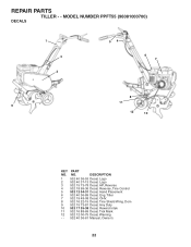
Tiller 7 532 19 48-08 Decal, OHV. 8 532 16 22-15 Decal, Tine Shield Wrng. Dom 9 532 15 73-81 Decal, Hvy Duty 10 532 17 35-38 Decal, Rewind Intek 11 532 16 88-69 Decal, Tick Mark 12 532 12 00-75 Decal, Warning - - 532 40 36-61 Manual, Owner's 22 NO. MODEL NUMBER PPFT55 (96081000700) DECALS 1 3 2 54 6 7 8 11 9 12 10 KEY PART NO. REPAIR PARTS TILLER - - DESCRIPTION 1 532 40 36-53 Decal, Logo 2 532 40 37-13 Decal, Logo 3 532 15 73-78 Decal, HP, Reverse 4 532 18 99-36 Decal, Reverse, Tine Control 5 532 12 04-31 Decal, Hand Placement 6 532 40 36-89 Decal, Eng.
Tiller 7 532 19 48-08 Decal, OHV. 8 532 16 22-15 Decal, Tine Shield Wrng. Dom 9 532 15 73-81 Decal, Hvy Duty 10 532 17 35-38 Decal, Rewind Intek 11 532 16 88-69 Decal, Tick Mark 12 532 12 00-75 Decal, Warning - - 532 40 36-61 Manual, Owner's 22 NO. MODEL NUMBER PPFT55 (96081000700) DECALS 1 3 2 54 6 7 8 11 9 12 10 KEY PART NO. REPAIR PARTS TILLER - - DESCRIPTION 1 532 40 36-53 Decal, Logo 2 532 40 37-13 Decal, Logo 3 532 15 73-78 Decal, HP, Reverse 4 532 18 99-36 Decal, Reverse, Tine Control 5 532 12 04-31 Decal, Hand Placement 6 532 40 36-89 Decal, Eng.


