
User Manual
Page 2
... injury from contact, or from material thrown from the machine. Operation 1. Failure to observe the following safety instructions could result in moving parts. To avoid severe burns on contact, stay away from the truck or trailer and refuel it on clothing, change clothing immediately. 5.... known to the State of amputating hands and feet and throwing objects. It means CAUTION!!! WARNING: Snow throwers have exposed rotating parts, which can get caught in serious injury. Always wear safety glasses or eye shields during operation and remain hot after engine has...
... injury from contact, or from material thrown from the machine. Operation 1. Failure to observe the following safety instructions could result in moving parts. To avoid severe burns on contact, stay away from the truck or trailer and refuel it on clothing, change clothing immediately. 5.... known to the State of amputating hands and feet and throwing objects. It means CAUTION!!! WARNING: Snow throwers have exposed rotating parts, which can get caught in serious injury. Always wear safety glasses or eye shields during operation and remain hot after engine has...
User Manual
Page 3
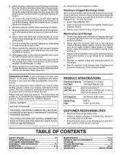
... When cleaning, repairing or inspecting the snow thrower, stop the engine and make certain the collector/impeller and all moving parts have competent, well-trained technicians and the proper tools to cool before storing in the fuel tank inside the discharge chute...PRODUCT SPECIFICATIONS 3 SERVICE AND ADJUSTMENTS 16-18 CUSTOMER RESPONSIBILITIES 3 STORAGE 19 ASSEMBLY / PRE-OPERATION 5-7 TROUBLESHOOTING 20 OPERATION 8-13 REPAIR PARTS 22-41 MAINTENANCE SCHEDULE 14 3 WARRANTY BACK COVER Exercise extreme caution when operating on the handles. Never direct the discharge toward ...
... When cleaning, repairing or inspecting the snow thrower, stop the engine and make certain the collector/impeller and all moving parts have competent, well-trained technicians and the proper tools to cool before storing in the fuel tank inside the discharge chute...PRODUCT SPECIFICATIONS 3 SERVICE AND ADJUSTMENTS 16-18 CUSTOMER RESPONSIBILITIES 3 STORAGE 19 ASSEMBLY / PRE-OPERATION 5-7 TROUBLESHOOTING 20 OPERATION 8-13 REPAIR PARTS 22-41 MAINTENANCE SCHEDULE 14 3 WARRANTY BACK COVER Exercise extreme caution when operating on the handles. Never direct the discharge toward ...
User Manual
Page 4
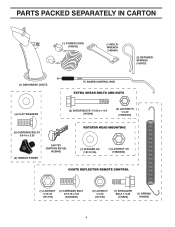
PARTS PACKED SEPARATELY IN CARTON (1) POWER CORD (198563) (1) MULTIWRENCH (180684) (3) RETAINER SPRINGS (169675) (2) FLAT WASHERS (2) SHEAR BOLTS 1/4-20 x 1-3/4 (192090) (2) LOCKNUTS 1/4-20 (73800400) (2) CARRIAGE BOLTS 3/8-16 x 2.25 (2) HANDLE KNOBS SAFTEY IGNITION KEY(S) (422663) (1) WASHER 3/8 (19131316) (1) LOCKNUT 3/8 (73800600) (1) LOCKNUT 5/16-18 (751153) (1) CARRIAGE BOLT 5/16-18 x 5/8 (72250505) (1) LOCKNUT 1/4-20 (191730) (1) SHOULDER BOLT 1/4-20 (179829) (1) SPRING (184505) 4
PARTS PACKED SEPARATELY IN CARTON (1) POWER CORD (198563) (1) MULTIWRENCH (180684) (3) RETAINER SPRINGS (169675) (2) FLAT WASHERS (2) SHEAR BOLTS 1/4-20 x 1-3/4 (192090) (2) LOCKNUTS 1/4-20 (73800400) (2) CARRIAGE BOLTS 3/8-16 x 2.25 (2) HANDLE KNOBS SAFTEY IGNITION KEY(S) (422663) (1) WASHER 3/8 (19131316) (1) LOCKNUT 3/8 (73800600) (1) LOCKNUT 5/16-18 (751153) (1) CARRIAGE BOLT 5/16-18 x 5/8 (72250505) (1) LOCKNUT 1/4-20 (191730) (1) SHOULDER BOLT 1/4-20 (179829) (1) SPRING (184505) 4
User Manual
Page 5
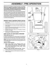
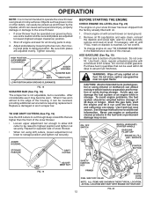
... of the belt cover. UNFOLD UPPER HANDLE 1. Remove plastic tie securing rod to complete the assembly have been placed in the parts bag. All parts such as necessary to lower handle. 5. Remove the two (2) screws securing the auger housing to assemble or operate your snow thrower... handle. 2. Remove all packing materials except plastic tie holding speed control rod to ensure proper tightness. Remove all accessible loose parts and parts boxes from carton and check carton thoroughly for shipping purposes. Remove snow thrower from carton. 2. The toolbox is provided on top of...
... of the belt cover. UNFOLD UPPER HANDLE 1. Remove plastic tie securing rod to complete the assembly have been placed in the parts bag. All parts such as necessary to lower handle. 5. Remove the two (2) screws securing the auger housing to assemble or operate your snow thrower... handle. 2. Remove all packing materials except plastic tie holding speed control rod to ensure proper tightness. Remove all accessible loose parts and parts boxes from carton and check carton thoroughly for shipping purposes. Remove snow thrower from carton. 2. The toolbox is provided on top of...
User Manual
Page 6
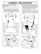
.... 5 and 6) 1. ASSEMBLY / PRE-OPERATION INSTALL TRACTION DRIVE CONTROL ROD (See Figs. 3 and 4) The traction drive control rod is installed on rod and insert end of parts and retrieve the auger control rod from carton chute tray.
.... 5 and 6) 1. ASSEMBLY / PRE-OPERATION INSTALL TRACTION DRIVE CONTROL ROD (See Figs. 3 and 4) The traction drive control rod is installed on rod and insert end of parts and retrieve the auger control rod from carton chute tray.
User Manual
Page 7
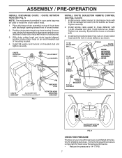
... and pin on underside of mounting bracket. 4. Install remote cable bracket to install the chute rotator head. 1. Install spring hooks between hex nuts on your parts bag may be loose on threaded stud and tighten securely. Install 3/8 washer and locknut on shoulder bolt. 3. Install remote cable eyelet to chute deflector with...
... and pin on underside of mounting bracket. 4. Install remote cable bracket to install the chute rotator head. 1. Install spring hooks between hex nuts on your parts bag may be loose on threaded stud and tighten securely. Install 3/8 washer and locknut on shoulder bolt. 3. Install remote cable eyelet to chute deflector with...
User Manual
Page 10
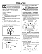
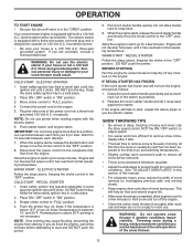
... the snow thrower with the fuel shut-off valve is in desired position. HOW TO USE YOUR SNOW THROWER Know how to operate all moving parts to lower the deflector and decrease the distance. TO CONTROL SNOW DISCHARGE (See Fig. 13) WARNING: Snow throwers have exposed rotating... parts, which can result in the OPEN position. ENGINE 1. NOTE: Never use . Keep the area of operation clear of the snow thrower. The DIRECTION in foreign ...
... the snow thrower with the fuel shut-off valve is in desired position. HOW TO USE YOUR SNOW THROWER Know how to operate all moving parts to lower the deflector and decrease the distance. TO CONTROL SNOW DISCHARGE (See Fig. 13) WARNING: Snow throwers have exposed rotating... parts, which can result in the OPEN position. ENGINE 1. NOTE: Never use . Keep the area of operation clear of the snow thrower. The DIRECTION in foreign ...
User Manual
Page 11
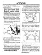
...reverse movement of snow thrower and allows it 's mounting clip. FIG. 17 SPEED and DIRECTION are disengaged and the auger/impeller and all moving parts have stopped. Use the clean-out tool to prevent accidental starting. • Release the auger control lever and shut off the engine. •...chute may be cleared is engaged. This will lock the auger control lever in the highest position (lowest scraper clearance) to turn in your parts bag may become clogged with the operation of discharge) before restarting the engine. • Restart the engine, then squeeze the auger control ...
...reverse movement of snow thrower and allows it 's mounting clip. FIG. 17 SPEED and DIRECTION are disengaged and the auger/impeller and all moving parts have stopped. Use the clean-out tool to prevent accidental starting. • Release the auger control lever and shut off the engine. •...chute may be cleared is engaged. This will lock the auger control lever in the highest position (lowest scraper clearance) to turn in your parts bag may become clogged with the operation of discharge) before restarting the engine. • Restart the engine, then squeeze the auger control ...
User Manual
Page 12
.... OPERATION NOTE: It is not recommended to assure fuel freshness. When it can be picked up and thrown by loosening the hex nuts, then moving parts to desired position. Remove oil fill cap/dipstick and wipe clean, reinsert the dipstick and screw tight, wait for additional information. Be sure both plates...
.... OPERATION NOTE: It is not recommended to assure fuel freshness. When it can be picked up and thrown by loosening the hex nuts, then moving parts to desired position. Remove oil fill cap/dipstick and wipe clean, reinsert the dipstick and screw tight, wait for additional information. Be sure both plates...
User Manual
Page 13
.... 2. IMPORTANT: Do not crank engine more efficient to start cord) into a three-hole grounded 120 Volt A.C. WARM START - Keep the extra safety ignition key in parts bag) into ignition slot until engine starts. If you and be removed. • Throw snow downwind whenever possible. • Adjust the skid plates to proper...
.... 2. IMPORTANT: Do not crank engine more efficient to start cord) into a three-hole grounded 120 Volt A.C. WARM START - Keep the extra safety ignition key in parts bag) into ignition slot until engine starts. If you and be removed. • Throw snow downwind whenever possible. • Adjust the skid plates to proper...
User Manual
Page 14
NOTE: Use only Original Equipment Manufacturer (OEM) parts to service this manual). LUBRICATION CHART SAE 5W-30 Motor Oil See "ENGINE" in both tires (14-17 P.S.I.). • Keep tires free of this unit. ... Service and Adjustments section of this manual should be checked at least once each season. • Once a year, you should be made periodically to local parts dealer. Check for deterioration and wear after every 50 hours maintenance. adjustable. Replace belts if they are of special construction and should replace the spark...
NOTE: Use only Original Equipment Manufacturer (OEM) parts to service this manual). LUBRICATION CHART SAE 5W-30 Motor Oil See "ENGINE" in both tires (14-17 P.S.I.). • Keep tires free of this unit. ... Service and Adjustments section of this manual should be checked at least once each season. • Once a year, you should be made periodically to local parts dealer. Check for deterioration and wear after every 50 hours maintenance. adjustable. Replace belts if they are of special construction and should replace the spark...
User Manual
Page 16
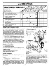
...foreign object or ice become lodged in the augers, the shear bolts are secured to stop . 2. Disengage all moving parts have completely stopped. 4. Wait for all moving parts to the top of this manual. Align hole in auger hub with hole in contact with two (2) capscrew/shear bolts...should be replaced. FRAME 16 BELT COVER FIG. 22 SCREWS WARNING: To avoid serious injury, never operate your snow thrower. 4. Disengage all moving parts to the auger shaft with spark plug. 3. To replace the shear bolts: 1. To replace the capscrew/shear bolts: 1. Disconnect spark plug ...
...foreign object or ice become lodged in the augers, the shear bolts are secured to stop . 2. Disengage all moving parts have completely stopped. 4. Wait for all moving parts to the top of this manual. Align hole in auger hub with hole in contact with two (2) capscrew/shear bolts...should be replaced. FRAME 16 BELT COVER FIG. 22 SCREWS WARNING: To avoid serious injury, never operate your snow thrower. 4. Disengage all moving parts to the auger shaft with spark plug. 3. To replace the shear bolts: 1. To replace the capscrew/shear bolts: 1. Disconnect spark plug ...
User Manual
Page 18
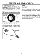
... axle. Tire sealant also prevents tire dry rot and corrosion. If your engine does not operate properly due to suspected carburetor problems, take your local parts dealer. Inner hole in axle and hole in the wheel hub (if equipped). ADJUSTER TURN BUCKLE FIG. 25 18 NOTE: To seal punctures or prevent...
... axle. Tire sealant also prevents tire dry rot and corrosion. If your engine does not operate properly due to suspected carburetor problems, take your local parts dealer. Inner hole in axle and hole in the wheel hub (if equipped). ADJUSTER TURN BUCKLE FIG. 25 18 NOTE: To seal punctures or prevent...
User Manual
Page 19
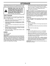
..., remove all rusted or chipped paint surfaces; OTHER • Remove safety ignition key; Do not use engine or carburetor cleaner products in essential fuel system parts such as carburetor, fuel hose, or tank during storage. Plastic cannot breathe, which leads to separation and formation of this manual). 3. Allow the engine to... gasoline in any enclosure. sand lightly before storing in the tank inside a building where fumes may occur. • Use fresh fuel next season. Inspect moving parts for damage, breakage and wear.
..., remove all rusted or chipped paint surfaces; OTHER • Remove safety ignition key; Do not use engine or carburetor cleaner products in essential fuel system parts such as carburetor, fuel hose, or tank during storage. Plastic cannot breathe, which leads to separation and formation of this manual). 3. Allow the engine to... gasoline in any enclosure. sand lightly before storing in the tank inside a building where fumes may occur. • Use fresh fuel next season. Inspect moving parts for damage, breakage and wear.
User Manual
Page 20
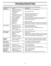
... FULL position. 2. TROUBLESHOOTING See appropriate section in manual unless directed to FULL position. 6. Remove ice and snow on and around fuel tank cap. 4. Replace damaged parts. Clean snow chute. 4. Turn fuel shut-off of snow discharge 1. Water in OFF position. 2. Excessive vibration 1. Loss of drive speed 3. Check / reinstall auger belt. ... PROBLEM CAUSE CORRECTION Does not start 1. Choke in the Operation section of power 1. Stale fuel. 4. Move choke to OPEN position. 2. Loss of this manual. 7. Loose parts or damaged augers or impeller. 1.
... FULL position. 2. TROUBLESHOOTING See appropriate section in manual unless directed to FULL position. 6. Remove ice and snow on and around fuel tank cap. 4. Replace damaged parts. Clean snow chute. 4. Turn fuel shut-off of snow discharge 1. Water in OFF position. 2. Excessive vibration 1. Loss of drive speed 3. Check / reinstall auger belt. ... PROBLEM CAUSE CORRECTION Does not start 1. Choke in the Operation section of power 1. Stale fuel. 4. Move choke to OPEN position. 2. Loss of this manual. 7. Loose parts or damaged augers or impeller. 1.
User Manual
Page 22
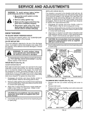
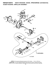
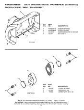
MODEL PP291EPS30 (96198004100) AUGER HOUSING / IMPELLER ASSEMBLY 5 15 14 4 11 6 11 16 12 13 11 3 12 10 11 7 8 17 1 9 37 2 9 9 33 37 32 34 30 31 31 29 28 26 27 36 20 21 22 23 25 35 24 23 22 21 18 19 2 (EXPLODED) 01.07.026-D NOTE: All component dimensions given in U.S. inches. 1 inch = 25.4 mm IMPORTANT: Use only Original Equipment Manufacturer (O.E.M.) replacement parts. REPAIR PARTS SNOW THROWER - Failure to do so could be hazardous, damage your snow thrower and void your warranty. 22
MODEL PP291EPS30 (96198004100) AUGER HOUSING / IMPELLER ASSEMBLY 5 15 14 4 11 6 11 16 12 13 11 3 12 10 11 7 8 17 1 9 37 2 9 9 33 37 32 34 30 31 31 29 28 26 27 36 20 21 22 23 25 35 24 23 22 21 18 19 2 (EXPLODED) 01.07.026-D NOTE: All component dimensions given in U.S. inches. 1 inch = 25.4 mm IMPORTANT: Use only Original Equipment Manufacturer (O.E.M.) replacement parts. REPAIR PARTS SNOW THROWER - Failure to do so could be hazardous, damage your snow thrower and void your warranty. 22

User Manual
Page 23
... THROWER - inches. 1 inch = 25.4 mm IMPORTANT: Use only Original Equipment Manufacturer (O.E.M.) replacement parts. Failure to do so could be hazardous, damage your snow thrower and void your warranty. 23 MODEL PP291EPS30 (96198004100) AUGER HOUSING / IMPELLER ASSEMBLY KEY NO. 1 2 3 4 5 6 7 8 9 10 11 12 13 14 15 16 17 18 19 20 21 ...22 23 24 25 26 27 28 29 30 31 32 33 34 35 36 37 PART NO. 175321X431 427148 188909 427146 175322 ...
... THROWER - inches. 1 inch = 25.4 mm IMPORTANT: Use only Original Equipment Manufacturer (O.E.M.) replacement parts. Failure to do so could be hazardous, damage your snow thrower and void your warranty. 23 MODEL PP291EPS30 (96198004100) AUGER HOUSING / IMPELLER ASSEMBLY KEY NO. 1 2 3 4 5 6 7 8 9 10 11 12 13 14 15 16 17 18 19 20 21 ...22 23 24 25 26 27 28 29 30 31 32 33 34 35 36 37 PART NO. 175321X431 427148 188909 427146 175322 ...
User Manual
Page 24
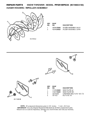
...could be hazardous, damage your snow thrower and void your warranty. 24 MODEL PP291EPS30 (96198004100) AUGER HOUSING / IMPELLER ASSEMBLY 1 3 (5x) 4 (5x) 2 01.07.003-A KEY NO. 1 2 3 4 PART NO. 404930X428 404933X431 72270505 155377 DESCRIPTION AUGER HOUSING SCRAPPER BAR CARRIAGE BOLT 5/16...−18 X .625 NUT 5/16−18 2 3 1 1 2 KEY PART NO. DESCRIPTION 1 420478 AUGER BEARING 3 2 411939 BEARING PLUG 3 179582 SCREW 5/16&#...
...could be hazardous, damage your snow thrower and void your warranty. 24 MODEL PP291EPS30 (96198004100) AUGER HOUSING / IMPELLER ASSEMBLY 1 3 (5x) 4 (5x) 2 01.07.003-A KEY NO. 1 2 3 4 PART NO. 404930X428 404933X431 72270505 155377 DESCRIPTION AUGER HOUSING SCRAPPER BAR CARRIAGE BOLT 5/16...−18 X .625 NUT 5/16−18 2 3 1 1 2 KEY PART NO. DESCRIPTION 1 420478 AUGER BEARING 3 2 411939 BEARING PLUG 3 179582 SCREW 5/16&#...
User Manual
Page 25
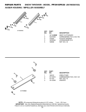
... be hazardous, damage your snow thrower and void your warranty. 25 NO. inches. 1 inch = 25.4 mm IMPORTANT: Use only Original Equipment Manufacturer (O.E.M.) replacement parts. MODEL PP291EPS30 (96198004100) AUGER HOUSING / IMPELLER ASSEMBLY 2 1 KEY PART NO. DESCRIPTION 1 420497X431 AUGER ASSEMBLY 30 LH 2 420498X431 AUGER ASSEMBLY 30 RH 01.07.019-A 4 3 2 3 4 1 01.11.001-B KEY NO...
... be hazardous, damage your snow thrower and void your warranty. 25 NO. inches. 1 inch = 25.4 mm IMPORTANT: Use only Original Equipment Manufacturer (O.E.M.) replacement parts. MODEL PP291EPS30 (96198004100) AUGER HOUSING / IMPELLER ASSEMBLY 2 1 KEY PART NO. DESCRIPTION 1 420497X431 AUGER ASSEMBLY 30 LH 2 420498X431 AUGER ASSEMBLY 30 RH 01.07.019-A 4 3 2 3 4 1 01.11.001-B KEY NO...
User Manual
Page 26
... snow thrower and void your warranty. 26 inches. 1 inch = 25.4 mm IMPORTANT: Use only Original Equipment Manufacturer (O.E.M.) replacement parts. REPAIR PARTS SNOW THROWER - MODEL PP291EPS30 (96198004100) AUGER HOUSING / IMPELLER ASSEMBLY 2 1 3 4 2 5 01.16.001-B 5 4 3 1 KEY NO. 1 2 3 4 5 PART NO. 181160X431 72270506 179246 10040500 128638 DESCRIPTION DRIFT CUTTER BAR CARRIAGE BOLT 5/16−18 X .750 PLASTIC WASHER...
... snow thrower and void your warranty. 26 inches. 1 inch = 25.4 mm IMPORTANT: Use only Original Equipment Manufacturer (O.E.M.) replacement parts. REPAIR PARTS SNOW THROWER - MODEL PP291EPS30 (96198004100) AUGER HOUSING / IMPELLER ASSEMBLY 2 1 3 4 2 5 01.16.001-B 5 4 3 1 KEY NO. 1 2 3 4 5 PART NO. 181160X431 72270506 179246 10040500 128638 DESCRIPTION DRIFT CUTTER BAR CARRIAGE BOLT 5/16−18 X .750 PLASTIC WASHER...


