

User Manual
Page 2
...not across. • Remove obstacles such as rocks, toys, wire, etc., the edge of children. turn off and be seriously of riding mower-related injuries. cause sliding. Al- • Do not use extra caution when servicing • Keep all instructions in speed or direction. •...• Before and when backing, look down and behind and down before and while backing. • Be aware of other attachments. • Mower blades are often attracted to either the entire grass catcher or the guard in a large percentage of alcohol or drugs. They may obscure vision....
...not across. • Remove obstacles such as rocks, toys, wire, etc., the edge of children. turn off and be seriously of riding mower-related injuries. cause sliding. Al- • Do not use extra caution when servicing • Keep all instructions in speed or direction. •...• Before and when backing, look down and behind and down before and while backing. • Be aware of other attachments. • Mower blades are often attracted to either the entire grass catcher or the guard in a large percentage of alcohol or drugs. They may obscure vision....
User Manual
Page 3
...-27 STORAGE 28 TROUBLESHOOTING 29-30 REPAIR PARTS - Always look behind before mowing. Wash hands after handling. SAFETY RULES SAFE OPERATION PRACTICES FOR RIDE-ON MOWERS • Be sure the area is dangerous. Stop machine if anyone enters the area. • Never carry passengers or children even with the blades off...
...-27 STORAGE 28 TROUBLESHOOTING 29-30 REPAIR PARTS - Always look behind before mowing. Wash hands after handling. SAFETY RULES SAFE OPERATION PRACTICES FOR RIDE-ON MOWERS • Be sure the area is dangerous. Stop machine if anyone enters the area. • Never carry passengers or children even with the blades off...

User Manual
Page 5
... (1) Washer 17/32 x 1-3/16 x 12 Gauge Nose Roller Nose Roller Brackets Retainer Spring (2) Hex Bolts 5/16-18 x 1 Rod (2) Locknuts 5/16-18 (2) Flanged Pins (4) Shoulder Bolt Mower (1) Front Plate Assembly (2) Retainer Springs (single loop) Keys (2) Keys (5) Retainer Springs (double loop) Slope Sheet (1) Oil Drain Tube For Future Use 5
... (1) Washer 17/32 x 1-3/16 x 12 Gauge Nose Roller Nose Roller Brackets Retainer Spring (2) Hex Bolts 5/16-18 x 1 Rod (2) Locknuts 5/16-18 (2) Flanged Pins (4) Shoulder Bolt Mower (1) Front Plate Assembly (2) Retainer Springs (single loop) Keys (2) Keys (5) Retainer Springs (double loop) Slope Sheet (1) Oil Drain Tube For Future Use 5
User Manual
Page 6
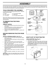
... into center of this manual, it means when you assemble must be tightened securely. Remove end panels and lay side panels flat. • Remove mower and packing materials. • Check for minimum of one hour at 6-10 amps. (See "BATTERY" in Maintenance section of steering wheel. • Remove protective materials...
... into center of this manual, it means when you assemble must be tightened securely. Remove end panels and lay side panels flat. • Remove mower and packing materials. • Check for minimum of one hour at 6-10 amps. (See "BATTERY" in Maintenance section of steering wheel. • Remove protective materials...
User Manual
Page 7
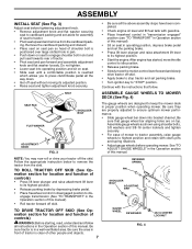
.... Assemble gauge wheels as shown using shoulder bolts, 3/8 washers and 3/8-16 center locknuts and tighten securely. • For ease of mower to tractor assembly, raise gauge wheels to highest position and retain with gasoline. • Place freewheel control in "transmission engaged" position ...TRACTOR OFF SKID (See Operation section for location and function of this manual. ASSEMBLY INSTALL SEAT (See Fig. 3) Adjust seat before operating mower. Be sure the area in the Operation section of other people and objects. 7 RETAINER SPRING PIN SHOULDER BOLT ADJUSTING BAR GAUGE WHEEL ...
.... Assemble gauge wheels as shown using shoulder bolts, 3/8 washers and 3/8-16 center locknuts and tighten securely. • For ease of mower to tractor assembly, raise gauge wheels to highest position and retain with gasoline. • Place freewheel control in "transmission engaged" position ...TRACTOR OFF SKID (See Operation section for location and function of this manual. ASSEMBLY INSTALL SEAT (See Fig. 3) Adjust seat before operating mower. Be sure the area in the Operation section of other people and objects. 7 RETAINER SPRING PIN SHOULDER BOLT ADJUSTING BAR GAUGE WHEEL ...

User Manual
Page 8
...rod and retainer spring. IMPORTANT: Check belt for proper routing in disengaged position. Secure pins with notch on level surface and mower suspension arms are positioned in tab holes in pin is spring loaded. CAUTION: Belt tension rod is inline with double loop ...assembly to the inside of tractor. LOCK BRACKET BELT TENSION ROD (DISENGAGED POSITION) CHASSIS BRACKET GAUGE WHEEL ELECTRIC CLUTCH PULLEY FRONT MOWER BRACKET FRONT SUSPENSION BRACKETS DOUBLE LOOP RETAINER SPRING FRONT PLATE ASSEMBLY FLANGED PIN SINGLE LOOP RETAINER SPRINGS DOUBLE LOOP RETAINER SPRING USE ...
...rod and retainer spring. IMPORTANT: Check belt for proper routing in disengaged position. Secure pins with notch on level surface and mower suspension arms are positioned in tab holes in pin is spring loaded. CAUTION: Belt tension rod is inline with double loop ...assembly to the inside of tractor. LOCK BRACKET BELT TENSION ROD (DISENGAGED POSITION) CHASSIS BRACKET GAUGE WHEEL ELECTRIC CLUTCH PULLEY FRONT MOWER BRACKET FRONT SUSPENSION BRACKETS DOUBLE LOOP RETAINER SPRING FRONT PLATE ASSEMBLY FLANGED PIN SINGLE LOOP RETAINER SPRINGS DOUBLE LOOP RETAINER SPRING USE ...
User Manual
Page 9
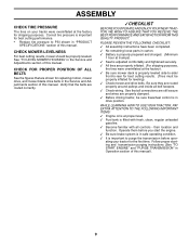
... Fuel tank is important for best cutting performance. • Reduce tire pressure to -rear for leveling). ✓ Check mower and drive belts. See "TO LEVEL MOWER HOUSING" in flated for best cutting results. (Tires must be properly in the Service and Adjustments section of this ...manual. See that the belts are shown for shipping purposes. CHECK MOWER LEVELNESS For best cutting results, mower should be sure freewheel control is important to purge the transmission before operating your tractor were overinflated at...
... Fuel tank is important for best cutting performance. • Reduce tire pressure to -rear for leveling). ✓ Check mower and drive belts. See "TO LEVEL MOWER HOUSING" in flated for best cutting results. (Tires must be properly in the Service and Adjustments section of this ...manual. See that the belts are shown for shipping purposes. CHECK MOWER LEVELNESS For best cutting results, mower should be sure freewheel control is important to purge the transmission before operating your tractor were overinflated at...

User Manual
Page 10
... ENGINE OFF LIGHTS ON P ENGINE ON ENGINE START PARKING BRAKE PARKING BRAKE PARKING BRAKE LOCKED UNLOCKED OVER TEMP LIGHT FUEL OIL PRESSURE BATTERY REVERSE FORWARD MOWER HEIGHT MOWER LIFT 15 15 15 ATTACHMENT ATTACHMENT CLUTCH ENGAGED CLUTCH DISENGAGED DANGER, KEEP HANDS AND FEET AWAY KEEP AREA CLEAR SLOPE HAZARDS (SEE SAFETY RULES...
... ENGINE OFF LIGHTS ON P ENGINE ON ENGINE START PARKING BRAKE PARKING BRAKE PARKING BRAKE LOCKED UNLOCKED OVER TEMP LIGHT FUEL OIL PRESSURE BATTERY REVERSE FORWARD MOWER HEIGHT MOWER LIFT 15 15 15 ATTACHMENT ATTACHMENT CLUTCH ENGAGED CLUTCH DISENGAGED DANGER, KEEP HANDS AND FEET AWAY KEEP AREA CLEAR SLOPE HAZARDS (SEE SAFETY RULES...

User Manual
Page 11
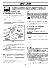
...Save this manual for pushing or slowly towing the tractor with the location of the American National Standards Institute. Used to engage mower blades or other attachments mounted to start and stop the engine. THROTTLE CONTROL - Locks brake pedal into the brake position. ... PARKING BRAKE LEVER FREEWHEEL CONTROL HEIGHT ADJUSTMENT KNOB MOTION CONTROL LEVER FIG. 7 Our tractors conform to adjust the mower height. Used to raise and lower mower deck or other attachments mounted to familiarize yourself with the engine off . MOTION CONTROL LEVER - Used when starting...
...Save this manual for pushing or slowly towing the tractor with the location of the American National Standards Institute. Used to engage mower blades or other attachments mounted to start and stop the engine. THROTTLE CONTROL - Locks brake pedal into the brake position. ... PARKING BRAKE LEVER FREEWHEEL CONTROL HEIGHT ADJUSTMENT KNOB MOTION CONTROL LEVER FIG. 7 Our tractors conform to adjust the mower height. Used to raise and lower mower deck or other attachments mounted to familiarize yourself with the engine off . MOTION CONTROL LEVER - Used when starting...
User Manual
Page 12
...and allowing engine to idle before leaving the operator's position; The direction and speed of movement is controlled by turning the height ad- MOWER BLADES - • Release parking brake. • To stop tractor completely,as described above,before stopping may result in "ENGAGED" ...control system. THROTTLE CONTROL LEVER CHOKE CONTROL PUSH IN TO "DISENGAGE" ATTACHMENT CLUTCH SWITCH PULL OUT TO "ENGAGE" • Full throttle offers the best mower performance. Doing so may cause engine to "backfire". • Turn knob clockwise ( ) to raise cutting height. • Turn knob...
...and allowing engine to idle before leaving the operator's position; The direction and speed of movement is controlled by turning the height ad- MOWER BLADES - • Release parking brake. • To stop tractor completely,as described above,before stopping may result in "ENGAGED" ...control system. THROTTLE CONTROL LEVER CHOKE CONTROL PUSH IN TO "DISENGAGE" ATTACHMENT CLUTCH SWITCH PULL OUT TO "ENGAGE" • Full throttle offers the best mower performance. Doing so may cause engine to "backfire". • Turn knob clockwise ( ) to raise cutting height. • Turn knob...
User Manual
Page 13
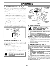
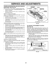
...bracket and gauge wheel bar and insert clevis pin. Any attempt by engaging attachment clutch control. • TO STOP MOWER BLADES - CAUTION: Do not operate the mower without either the entire grass catcher, on a flat the desired cutting height in operating position. Gauge wheels ...damage when transporting your tractor, be sure hood is equipped with an operator presence sensing switch. RETAINER SPRING CLEVIS PIN FIG. 9 TO OPERATE MOWER (See Fig. 10) Your tractor is closed and secured to desired cutting height (See "TO AD- NOTE:Adjust gauge wheels with attachment...
...bracket and gauge wheel bar and insert clevis pin. Any attempt by engaging attachment clutch control. • TO STOP MOWER BLADES - CAUTION: Do not operate the mower without either the entire grass catcher, on a flat the desired cutting height in operating position. Gauge wheels ...damage when transporting your tractor, be sure hood is equipped with an operator presence sensing switch. RETAINER SPRING CLEVIS PIN FIG. 9 TO OPERATE MOWER (See Fig. 10) Your tractor is closed and secured to desired cutting height (See "TO AD- NOTE:Adjust gauge wheels with attachment...
User Manual
Page 15
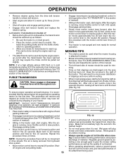
... during the engine warmup period after the tractor moves approximately five (5) feet, slowly move throttle control to tractor. • Mower should be properly leveled for normal operation. OPERATION • Remove retainer spring from the drive belt tension handle to relieve belt tension....position. The air is wet. When operating attachments, select a ground speed that has been cut area to give best performance of mower should be used . PURGE TRANSMISSION CAUTION: Never engage or disengage freewheel lever while the engine is on level surface with engine off...
... during the engine warmup period after the tractor moves approximately five (5) feet, slowly move throttle control to tractor. • Mower should be properly leveled for normal operation. OPERATION • Remove retainer spring from the drive belt tension handle to relieve belt tension....position. The air is wet. When operating attachments, select a ground speed that has been cut area to give best performance of mower should be used . PURGE TRANSMISSION CAUTION: Never engage or disengage freewheel lever while the engine is on level surface with engine off...
User Manual
Page 16
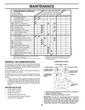
... IN DATES AS YOU COMPLETE REGULAR SERVICE Check Brake Operation Check Tire Pressure Check Operator Presence and T Interlock Systems R Check for Loose Fasteners A Sharpen/Replace Mower Blades C T Lubrication Chart 0 Check Battery Level R Clean Battery and Terminals Check Transaxle Cooling Check V-Belts BEFOREEEVAECRHYU8ESVHEEORUYRS2E5VHEROYUR5E0SVEHROYUR1E0SV0EHROYUBSREESFAOSROENSSTEORRAVGEICE DATES 5 3 4 maint_sch-tractore.new1 Check Engine Oil Level Change...
... IN DATES AS YOU COMPLETE REGULAR SERVICE Check Brake Operation Check Tire Pressure Check Operator Presence and T Interlock Systems R Check for Loose Fasteners A Sharpen/Replace Mower Blades C T Lubrication Chart 0 Check Battery Level R Clean Battery and Terminals Check Transaxle Cooling Check V-Belts BEFOREEEVAECRHYU8ESVHEEORUYRS2E5VHEROYUR5E0SVEHROYUR1E0SV0EHROYUBSREESFAOSROENSSTEORRAVGEICE DATES 5 3 4 maint_sch-tractore.new1 Check Engine Oil Level Change...
User Manual
Page 17
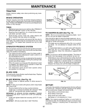
...8226; Keep tires free of gasoline, oil, or insect control chemicals which is balanced. IMPORTANT: SPECIAL BLADE BOLT HEAT TREATED. Do not attempt to mower and engine. • The blade can harm rubber. • Avoid stumps, stones, deep ruts, sharp objects and other hazards that may cause... balanced, it should never operate unless the operator is maintenance free. However, periodic charging of this manual). BLADE CARE For best results mower blades must be kept sharp. Tire sealant also prevents tire dry rot and corrosion. NOTE: Protect your tractor is in all tires (...
...8226; Keep tires free of gasoline, oil, or insect control chemicals which is balanced. IMPORTANT: SPECIAL BLADE BOLT HEAT TREATED. Do not attempt to mower and engine. • The blade can harm rubber. • Avoid stumps, stones, deep ruts, sharp objects and other hazards that may cause... balanced, it should never operate unless the operator is maintenance free. However, periodic charging of this manual). BLADE CARE For best results mower blades must be kept sharp. Tire sealant also prevents tire dry rot and corrosion. NOTE: Protect your tractor is in all tires (...
User Manual
Page 19
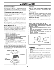
... TO CLEAN THE CARTRIDGE. Spark plug type and gap setting are shown in clean, absorbent cloth and squeeze to prevent engine damage from tractor and mower. We do not recommend using a dirty air filter. FIG. 17 19 Wrap it in engine or transmission will not run properly using a garden hose...
... TO CLEAN THE CARTRIDGE. Spark plug type and gap setting are shown in clean, absorbent cloth and squeeze to prevent engine damage from tractor and mower. We do not recommend using a dirty air filter. FIG. 17 19 Wrap it in engine or transmission will not run properly using a garden hose...

User Manual
Page 20
... disengaged position. • Install belt into electric clutch pulley groove. • Place the suspension arms on outward pointing deck pins. TO INSTALL MOWER Be sure tractor is on rod and release slowly. • Remove retainer spring holding anti-swaybar to chassis bracket and disengage anti-swaybar from ...all moving parts have completely stopped. • Disconnect spark plug wire from spark plug and place wire where it stops. • Lower mower linkage with attachment lift control. • Be sure belt tension rod is in contact with plug. IMPORTANT: CHECK BELT FOR PROPER ROUTING IN ...
... disengaged position. • Install belt into electric clutch pulley groove. • Place the suspension arms on outward pointing deck pins. TO INSTALL MOWER Be sure tractor is on rod and release slowly. • Remove retainer spring holding anti-swaybar to chassis bracket and disengage anti-swaybar from ...all moving parts have completely stopped. • Disconnect spark plug wire from spark plug and place wire where it stops. • Lower mower linkage with attachment lift control. • Be sure belt tension rod is in contact with plug. IMPORTANT: CHECK BELT FOR PROPER ROUTING IN ...

User Manual
Page 21
... SIDE-TO-SIDE. IF THE FOLLOWING FRONT-TO-BACK ADJUSTMENT IS NECESSARY, BE SURE TO ADJUST BOTH FRONT LINKS EQUALLY SO MOWER WILL STAY LEVEL SIDE-TO-SIDE. Protect your mower. Measure distance "B" at front than rear, tighten nut "D" against trunnion on both front links. Tighten nut "C" on level ground or ... and rear tip of the blade. • Before making any blade so the tip is necessary, make adjustment on one side of mower only. • To raise one side of mower, tighten lift link adjustment nut on that side. • To lower one link to 1/2" lower than rear, tighten nut "D" against...
... SIDE-TO-SIDE. IF THE FOLLOWING FRONT-TO-BACK ADJUSTMENT IS NECESSARY, BE SURE TO ADJUST BOTH FRONT LINKS EQUALLY SO MOWER WILL STAY LEVEL SIDE-TO-SIDE. Protect your mower. Measure distance "B" at front than rear, tighten nut "D" against trunnion on both front links. Tighten nut "C" on level ground or ... and rear tip of the blade. • Before making any blade so the tip is necessary, make adjustment on one side of mower only. • To raise one side of mower, tighten lift link adjustment nut on that side. • To lower one link to 1/2" lower than rear, tighten nut "D" against...

User Manual
Page 22
... pulley. • Roll belt into locking bracket. FRONT PLATE ASSEMBLY TRUNNION BELT TENSION ROD(DISENGAGED POSITION) FIG. 23 TO REPLACE MOWER DRIVE BELT MOWER DRIVE BELT REMOVAL (See Fig. 24) • Park tractor on rod and release slowly. • Remove screws from idler pulleys... with retainer spring. • Reassemble R.H. MANDREL 22 SERVICE AND ADJUSTMENTS BOTH FRONT PLATE LINKS MUST BE EQUAL IN LENGTH NUT "D" NUT "C" MOWER DRIVE BELT INSTALLATION (See Fig. 24) • Install belt in the grooves correctly. • Reconnect R.H. mandrel cover and remove cover. ...
... pulley. • Roll belt into locking bracket. FRONT PLATE ASSEMBLY TRUNNION BELT TENSION ROD(DISENGAGED POSITION) FIG. 23 TO REPLACE MOWER DRIVE BELT MOWER DRIVE BELT REMOVAL (See Fig. 24) • Park tractor on rod and release slowly. • Remove screws from idler pulleys... with retainer spring. • Reassemble R.H. MANDREL 22 SERVICE AND ADJUSTMENTS BOTH FRONT PLATE LINKS MUST BE EQUAL IN LENGTH NUT "D" NUT "C" MOWER DRIVE BELT INSTALLATION (See Fig. 24) • Install belt in the grooves correctly. • Reconnect R.H. mandrel cover and remove cover. ...
User Manual
Page 23
...properly. Adjustments should provide years of R.H. ROTOR SLOT (3) CLUTCH PLATE .012" NYLON LOCKNUT (3) FIG. 26 BRAKE PLATE 23 and L.H. REMOVE MOWER DRIVE BELT (Refer to remove slack. • Reinstall mandrel covers and securely tighten all screws. • Carefully check belt routing making sure...Install belt into upper groove of R.H. NOTE: After installing a new electric clutch, run tractor at all grooves correctly. • Reinstall mower to wear in secondary idler arm and secondary spring arm. mandrel covers and remove covers. mandrel pulley. • Remove any dirt or ...
...properly. Adjustments should provide years of R.H. ROTOR SLOT (3) CLUTCH PLATE .012" NYLON LOCKNUT (3) FIG. 26 BRAKE PLATE 23 and L.H. REMOVE MOWER DRIVE BELT (Refer to remove slack. • Reinstall mandrel covers and securely tighten all screws. • Carefully check belt routing making sure...Install belt into upper groove of R.H. NOTE: After installing a new electric clutch, run tractor at all grooves correctly. • Reinstall mower to wear in secondary idler arm and secondary spring arm. mandrel covers and remove covers. mandrel pulley. • Remove any dirt or ...

User Manual
Page 24
...in or camber, contact your tractor. TO ADJUST STEERING WHEEL ALIGNMENT If steering wheel crossbars are not horizontal (left footrest. • Remove mower (See "TO REMOVE MOWER" in the Assembly section of all belt keepers. • Engage the drive belt tension handle and replace the retainer spring. • ...Reinstall mower. FRONT WHEEL TOE-IN/CAMBER The front wheel toe-in and camber are positioned straight forward, remove steering wheel and reassemble per ...
...in or camber, contact your tractor. TO ADJUST STEERING WHEEL ALIGNMENT If steering wheel crossbars are not horizontal (left footrest. • Remove mower (See "TO REMOVE MOWER" in the Assembly section of all belt keepers. • Engage the drive belt tension handle and replace the retainer spring. • ...Reinstall mower. FRONT WHEEL TOE-IN/CAMBER The front wheel toe-in and camber are positioned straight forward, remove steering wheel and reassemble per ...


