
User Manual
Page 8
...safe operating condition. ✓ Be sure Operator Presence System and Reverse Operation System (ROS) are shown for leveling). ✓ Check mower and drive belts. CHECK DECK LEVELNESS For best cutting results, mower housing should be properly inflated for replacing motion and mower blade drive... belts in flated. (For shipping purposes, the tires were overinflated at proper level. ✓ Fuel tank is important for best cutting ...
...safe operating condition. ✓ Be sure Operator Presence System and Reverse Operation System (ROS) are shown for leveling). ✓ Check mower and drive belts. CHECK DECK LEVELNESS For best cutting results, mower housing should be properly inflated for replacing motion and mower blade drive... belts in flated. (For shipping purposes, the tires were overinflated at proper level. ✓ Fuel tank is important for best cutting ...
User Manual
Page 19
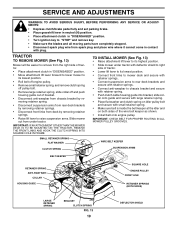
...WASHER WIRE BELT KEEPER CLUTCH SPRING SUSPENSION ARMS BELT KEEPER RETAINER SPRING ANTI-SWAY BAR COLLAR HOUSING GUIDE SQUARE HOLE ENGINE PULLEY FRONT LINK RETAINER SPRINGS (BOTH SIDES) LARGE RETAINER SPRING BRACKET 02845 CLUTCH SPRING FIG. 13 19 DEFLECTOR SHIELD IMPORTANT: IF AN ATTACHMENT OTHER THAN THE MOWER DECK IS ...TO BE MOUNTED ON THE TRACTOR, REMOVE THE FRONT LINKS AND HOOK THE CLUTCH SPRING INTO SQUARE HOLE IN FRAME. TRACTOR TO REMOVE MOWER (See Fig. 13) Mower will be easier to remove from the right side of the wire belt keeper as shown....
...WASHER WIRE BELT KEEPER CLUTCH SPRING SUSPENSION ARMS BELT KEEPER RETAINER SPRING ANTI-SWAY BAR COLLAR HOUSING GUIDE SQUARE HOLE ENGINE PULLEY FRONT LINK RETAINER SPRINGS (BOTH SIDES) LARGE RETAINER SPRING BRACKET 02845 CLUTCH SPRING FIG. 13 19 DEFLECTOR SHIELD IMPORTANT: IF AN ATTACHMENT OTHER THAN THE MOWER DECK IS ...TO BE MOUNTED ON THE TRACTOR, REMOVE THE FRONT LINKS AND HOOK THE CLUTCH SPRING INTO SQUARE HOLE IN FRAME. TRACTOR TO REMOVE MOWER (See Fig. 13) Mower will be easier to remove from the right side of the wire belt keeper as shown....
User Manual
Page 20
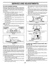
... NUT "E" SUSPENSION ARM LIFT LINK ADJUSTMENT NUT FRONT LINKS FIG. 17 FIG. 15 FRONT-TO-BACK ADJUSTMENT (See Figs. 16 and 17) IMPORTANT: DECK MUST BE LEVEL SIDE-TO-SIDE. Check adjustment on right side of turns. To obtain the best cutting results, the mower housing should be the... necessary, make adjustment on one side of mower only. • To raise one side of mower, tighten lift link adjustment nut on that side. BELT REMOVAL • Place attachment clutch in length. • When distance "D" is 1/8" to -side adjustment. Park the tractor on level ground or driveway. ...
... NUT "E" SUSPENSION ARM LIFT LINK ADJUSTMENT NUT FRONT LINKS FIG. 17 FIG. 15 FRONT-TO-BACK ADJUSTMENT (See Figs. 16 and 17) IMPORTANT: DECK MUST BE LEVEL SIDE-TO-SIDE. Check adjustment on right side of turns. To obtain the best cutting results, the mower housing should be the... necessary, make adjustment on one side of mower only. • To raise one side of mower, tighten lift link adjustment nut on that side. BELT REMOVAL • Place attachment clutch in length. • When distance "D" is 1/8" to -side adjustment. Park the tractor on level ground or driveway. ...

User Manual
Page 26
...connections. 3. Turn ignition key to slower speed. 3. Clean around mandrels. 1. Replace idler pulley. 4. Mower drive belt worn. 9. Level mower deck. 5. Faulty regulator (if so equipped). 4. Reverse operation system (ROS) is not "ON" while mower or other...6. Bad battery cell(s). 2. Engine continues to open vent holes. Mower deck not level. 3. Level mower deck. 3. Replace blade mandrel. 5. Obstruction in "FAST" position. 2. Remove obstruction. 2. Replace mower drive belt. 3. Replace blade mandrel. Poor grass discharge 1. Blades improperly installed. ...
...connections. 3. Turn ignition key to slower speed. 3. Clean around mandrels. 1. Replace idler pulley. 4. Mower drive belt worn. 9. Level mower deck. 5. Faulty regulator (if so equipped). 4. Reverse operation system (ROS) is not "ON" while mower or other...6. Bad battery cell(s). 2. Engine continues to open vent holes. Mower deck not level. 3. Level mower deck. 3. Replace blade mandrel. 5. Obstruction in "FAST" position. 2. Remove obstruction. 2. Replace mower drive belt. 3. Replace blade mandrel. Poor grass discharge 1. Blades improperly installed. ...
Parts List
Page 15
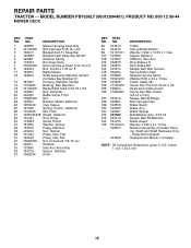
... Spacer Bolt/Washer Asm. 5/16-18 Keeper Belt Rh Mandrel Brake Guard Washer 13/32 x 2 x 10 Ga. PRODUCT NO. 960 12 00-44 MOWER DECK KEY PART NO. Sway Bar 4 192568 Bracket Deck Sway Bar 38"/42" 5 4939M Retainer Spring 6 178024 Bar Sway Deck 7 73800500 Nut Lock Hex w/Insert 5/16-...Idler Arm Assembly 56 165723 Spacer, Retainer 67 106932X Knob KEY PART NO. Mandrel Assembly (Includes Housing, Shaft and Shaft Hardware Only - MODEL NUMBER PB1638LT (96012004401). REPAIR PARTS TRACTOR - - NO. 68 193214 72 193216 89 19131311 107 133502 108 133503 122 192575 123 192576 144 193414 148 169022...
... Spacer Bolt/Washer Asm. 5/16-18 Keeper Belt Rh Mandrel Brake Guard Washer 13/32 x 2 x 10 Ga. PRODUCT NO. 960 12 00-44 MOWER DECK KEY PART NO. Sway Bar 4 192568 Bracket Deck Sway Bar 38"/42" 5 4939M Retainer Spring 6 178024 Bar Sway Deck 7 73800500 Nut Lock Hex w/Insert 5/16-...Idler Arm Assembly 56 165723 Spacer, Retainer 67 106932X Knob KEY PART NO. Mandrel Assembly (Includes Housing, Shaft and Shaft Hardware Only - MODEL NUMBER PB1638LT (96012004401). REPAIR PARTS TRACTOR - - NO. 68 193214 72 193216 89 19131311 107 133502 108 133503 122 192575 123 192576 144 193414 148 169022...


