
User Manual
Page 1
£moe op d • OWNER'S MANUAL MODEL NO. Before you start the engine, read and understand this Owner's Manual. 164744 2.4.98 TR PRINTED IN U.S.A. CHDR500C 5 HP 17 inch Tiller • Assembly • Operation • Customer Responsibilities • Service and Adjustments • Storage • Troubleshooting • Repair Parts Poulan This product has a low emission engine which operates differently from previously built engines.
£moe op d • OWNER'S MANUAL MODEL NO. Before you start the engine, read and understand this Owner's Manual. 164744 2.4.98 TR PRINTED IN U.S.A. CHDR500C 5 HP 17 inch Tiller • Assembly • Operation • Customer Responsibilities • Service and Adjustments • Storage • Troubleshooting • Repair Parts Poulan This product has a low emission engine which operates differently from previously built engines.
User Manual
Page 2
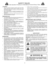
... with fuel in place. • Keep children and pets away. • Do not overload the machine capacity by the manufacturer of all moving parts have stopped. Never fill fuel tank indoors. • Replace gasoline cap securely and clean up , transporting, adjusting or making repairs. Do not ...slippery surfaces. • Handle fuel with the controls and the proper use care when backing. • Never allow bystanders near or under rotating parts. • Exercise extreme caution when operating on electric motors. • Do not run the engine indoors; Be thoroughly familiar with care; it...
... with fuel in place. • Keep children and pets away. • Do not overload the machine capacity by the manufacturer of all moving parts have stopped. Never fill fuel tank indoors. • Replace gasoline cap securely and clean up , transporting, adjusting or making repairs. Do not ...slippery surfaces. • Handle fuel with the controls and the proper use care when backing. • Never allow bystanders near or under rotating parts. • Exercise extreme caution when operating on electric motors. • Do not run the engine indoors; Be thoroughly familiar with care; it...
User Manual
Page 4
... The Warranty period for any product which vary from locale to locale. Exclusions: Excluded from this product as defined in replacing parts, any power equipment unit or attachment are belts, tines, tine adapters, normal wear, normal adjustments, standard hardware and normal ... SPECIFICATIONS CUSTOMER RESPONSIBILITIES WARRANTY ASSEMBLY OPERATION 2 3 3,13-15 4 5-7 8-12 MAINTENANCE SCHEDULE SERVICE & ADJUSTMENTS STORAGE TROUBLESHOOTING REPAIR PARTS-TILLER 13 15-18 19 20 21-27 LIMITED WARRANTY The Manufacturer warrants to the original consumer purchaser that term as manufactured is...
... The Warranty period for any product which vary from locale to locale. Exclusions: Excluded from this product as defined in replacing parts, any power equipment unit or attachment are belts, tines, tine adapters, normal wear, normal adjustments, standard hardware and normal ... SPECIFICATIONS CUSTOMER RESPONSIBILITIES WARRANTY ASSEMBLY OPERATION 2 3 3,13-15 4 5-7 8-12 MAINTENANCE SCHEDULE SERVICE & ADJUSTMENTS STORAGE TROUBLESHOOTING REPAIR PARTS-TILLER 13 15-18 19 20 21-27 LIMITED WARRANTY The Manufacturer warrants to the original consumer purchaser that term as manufactured is...
User Manual
Page 5
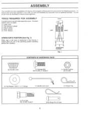
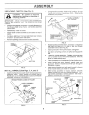
... ASSEMBLY A socket wrench set will make assembly easier. To ensure safe and proper operation of your tiller, all parts and hardware you are listed. (1) Utility knife (1) Tire pressure gauge (1) Pair of those parts left hand is mentioned in the operating position (standing behind tiller handles). ASSEMBLY Your new tiller has been assembled...
... ASSEMBLY A socket wrench set will make assembly easier. To ensure safe and proper operation of your tiller, all parts and hardware you are listed. (1) Utility knife (1) Tire pressure gauge (1) Pair of those parts left hand is mentioned in the operating position (standing behind tiller handles). ASSEMBLY Your new tiller has been assembled...
User Manual
Page 6
Remove packing material from carton. Be sure handle lock remains in front part of carton and lay panels flat. Cut down . This will make it easier to aid in keeping lock in place until handle assembly is lowered ...
Remove packing material from carton. Be sure handle lock remains in front part of carton and lay panels flat. Cut down . This will make it easier to aid in keeping lock in place until handle assembly is lowered ...
User Manual
Page 11
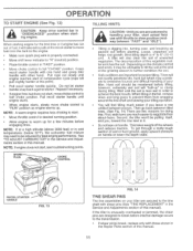
... engine warms up for a few minutes before internal damage occurs to the transmission. • If shear pin(s) break, replace only with throttle in the Repair Parts section of the growing season to further condition the soil. • Soil conditions are much easier if you leave a row untilled between passes. NOTE: If...
... engine warms up for a few minutes before internal damage occurs to the transmission. • If shear pin(s) break, replace only with throttle in the Repair Parts section of the growing season to further condition the soil. • Soil conditions are much easier if you leave a row untilled between passes. NOTE: If...
User Manual
Page 19
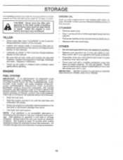
... follow the mix ratio found on stabilizer container. IMPORTANT: NEVER COVER TILLER WHILE ENGINE AND EXHAUST AREAS ARE STILL WARM. 19 Inspect moving parts for 30 days or more. ALSO, EXPERIENCE INDICATES THAT ALCOHOL BLENDED FUELS (CALLED GASOHOL OR USING ETHANOL OR METHANOL) CAN ATTRACT MOISTURE WHICH... may reach an open flame or spark. ENGINE FUEL SYSTEM IMPORTANT: IT IS IMPORTANT TO PREVENT GUM DEPOSITS FROM FORMING IN ESSENTIAL FUEL SYSTEM PARTS SUCH AS THE CARBURETOR, FUEL FILTER, FUEL HOSE, OR TANK DURING STORAGE. Add stabilizer to give protection from one season to rust. C`...
... follow the mix ratio found on stabilizer container. IMPORTANT: NEVER COVER TILLER WHILE ENGINE AND EXHAUST AREAS ARE STILL WARM. 19 Inspect moving parts for 30 days or more. ALSO, EXPERIENCE INDICATES THAT ALCOHOL BLENDED FUELS (CALLED GASOHOL OR USING ETHANOL OR METHANOL) CAN ATTRACT MOISTURE WHICH... may reach an open flame or spark. ENGINE FUEL SYSTEM IMPORTANT: IT IS IMPORTANT TO PREVENT GUM DEPOSITS FROM FORMING IN ESSENTIAL FUEL SYSTEM PARTS SUCH AS THE CARBURETOR, FUEL FILTER, FUEL HOSE, OR TANK DURING STORAGE. Add stabilizer to give protection from one season to rust. C`...
User Manual
Page 21
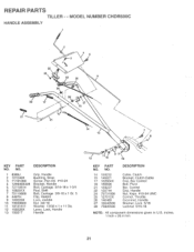
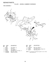
REPAIR PARTS TILLER - - NO. NO. 14 159232 15 145821 17 102604X 18 150696 21 159227 22 150744 24 73731000 25 127012X 26 146480...Control, Throttle Grommet, Handle Washer, Lock 5/16 Locknut 5/16-18 NOTE: All component dimensions given in U.S. MODEL NUMBER CHDR500C HANDLE ASSEMBLY 2 4 5 c 25 24 22 26 6 26 28 17 27 15 21 14 7 13 KEY PART NO. inches. 1 inch = 25.4 mm 21 DESCRIPTION 1 8389J Grip, Handle 2 121248X Bushing, Snap 3 71191008... Nut 3/8-16 11 19131611 Washer 13/32 x 1 x 11 Ga. 12 109228X Lever, Lock, Handle 13 150217 Handle o 12 110 9 18 KEY PART NO.
REPAIR PARTS TILLER - - NO. NO. 14 159232 15 145821 17 102604X 18 150696 21 159227 22 150744 24 73731000 25 127012X 26 146480...Control, Throttle Grommet, Handle Washer, Lock 5/16 Locknut 5/16-18 NOTE: All component dimensions given in U.S. MODEL NUMBER CHDR500C HANDLE ASSEMBLY 2 4 5 c 25 24 22 26 6 26 28 17 27 15 21 14 7 13 KEY PART NO. inches. 1 inch = 25.4 mm 21 DESCRIPTION 1 8389J Grip, Handle 2 121248X Bushing, Snap 3 71191008... Nut 3/8-16 11 19131611 Washer 13/32 x 1 x 11 Ga. 12 109228X Lever, Lock, Handle 13 150217 Handle o 12 110 9 18 KEY PART NO.
User Manual
Page 22
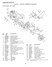
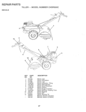
MODEL NUMBER CHDR500C MAINFRAME, LEFT SIDE 3 , 6( 2 '6( 3 l r•z :- 4 NV ,I6 6( 2 j ik----r4A1.1.1 \ \V ' -•k '.•:,..13„ REPAIR PARTS TILLER - -
MODEL NUMBER CHDR500C MAINFRAME, LEFT SIDE 3 , 6( 2 '6( 3 l r•z :- 4 NV ,I6 6( 2 j ik----r4A1.1.1 \ \V ' -•k '.•:,..13„ REPAIR PARTS TILLER - -
User Manual
Page 23
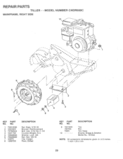
VA .: o/y::: -- --- Washer, Lock 3/8 Nut, Hex 3/8-16 Clip, Hairpin Rivet, Drilled KEY PART NO. ON•. /....s. ....s. --. .. ....S. \ , -S A •••• S. % r /7- MODEL NUMBER CHDR500C MAINFRAME, RIGHT SIDE 10 J,'• O 9 8 ( ii I, /1 1 . - - - -. REPAIR PARTS TILLER - - NO. 9 102190X 150750 795R 10 DESCRIPTION Tire Rim Tire Valve Engine, Briggs & Stratton Model No. 137202 NOTE: All component dimensions given in U.S.inches...
VA .: o/y::: -- --- Washer, Lock 3/8 Nut, Hex 3/8-16 Clip, Hairpin Rivet, Drilled KEY PART NO. ON•. /....s. ....s. --. .. ....S. \ , -S A •••• S. % r /7- MODEL NUMBER CHDR500C MAINFRAME, RIGHT SIDE 10 J,'• O 9 8 ( ii I, /1 1 . - - - -. REPAIR PARTS TILLER - - NO. 9 102190X 150750 795R 10 DESCRIPTION Tire Rim Tire Valve Engine, Briggs & Stratton Model No. 137202 NOTE: All component dimensions given in U.S.inches...
User Manual
Page 24
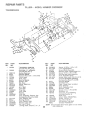
... 106147X 51 17720408 52 73220500 53 122204X - - 6066J Spacer 0.765 x 1.125 x 1.23 Chain #35-50 Pitch Ground Shaft Assembly Bearing, Shaft, Ground Drive R.H. MODEL NUMBER CHDR500C TRANSMISSION r 2 6 5 4 12 13 y 141"41N 14 1110 9 5 7 16 18 23 24\ 25 )%1T* 24 Tv es 24 -- 1 19 2 28 7 29... 2nd Gear, Reverse Shaft, Reduction (1st) Washer, Thrust Spacer 1.01 x 1.75 x 0.760 Seal Asm. Oil Gearcase, R.H. inches 24 1 inch = 25.4 mm KEY PART NO. w/Bearing (Includes Key No. 8) Shaft, Tine Chain, Roller #50-50 Pitch Screw 1/4-20 x 1/2 Nut, Hex 5/16-18 Kit, Bearing, Tine Shaft Grease, ...
... 106147X 51 17720408 52 73220500 53 122204X - - 6066J Spacer 0.765 x 1.125 x 1.23 Chain #35-50 Pitch Ground Shaft Assembly Bearing, Shaft, Ground Drive R.H. MODEL NUMBER CHDR500C TRANSMISSION r 2 6 5 4 12 13 y 141"41N 14 1110 9 5 7 16 18 23 24\ 25 )%1T* 24 Tv es 24 -- 1 19 2 28 7 29... 2nd Gear, Reverse Shaft, Reduction (1st) Washer, Thrust Spacer 1.01 x 1.75 x 0.760 Seal Asm. Oil Gearcase, R.H. inches 24 1 inch = 25.4 mm KEY PART NO. w/Bearing (Includes Key No. 8) Shaft, Tine Chain, Roller #50-50 Pitch Screw 1/4-20 x 1/2 Nut, Hex 5/16-18 Kit, Bearing, Tine Shaft Grease, ...
User Manual
Page 25
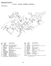
... Hex 5/16-18 Washer, Lock 5/16 Bolt, Carriage 5/16-18 x 1-1/4 Bracket, Shield Tine Shield, Side, Outer R.H. KEY PART NO. REPAIR PARTS TILLER - - NO. 1 98000129 2 161415X428 3 8393J 4 12000036 5 72140506 6 8394J 7 8392J 8 109230X 9 102326X428 10 104085X428 ... Bolt, Carriage 1/4-20 x 1/2 Gr. 5 Cap, Vinyl Pad, Idler Shield, Leveling Pin, Hinge NOTE: All component dimensions given in U.S. inches. 1 inch = 25.4 mm 25 MODEL NUMBER CHDR500C TINE SHIELD 24 24 1 3 5 13 14 ,• • ; • ; -. 'a .0"0* • 2 1 6 7 8 5 9 Y 12 A; , / , , ,•/, 114 • ' :1.01 ...
... Hex 5/16-18 Washer, Lock 5/16 Bolt, Carriage 5/16-18 x 1-1/4 Bracket, Shield Tine Shield, Side, Outer R.H. KEY PART NO. REPAIR PARTS TILLER - - NO. 1 98000129 2 161415X428 3 8393J 4 12000036 5 72140506 6 8394J 7 8392J 8 109230X 9 102326X428 10 104085X428 ... Bolt, Carriage 1/4-20 x 1/2 Gr. 5 Cap, Vinyl Pad, Idler Shield, Leveling Pin, Hinge NOTE: All component dimensions given in U.S. inches. 1 inch = 25.4 mm 25 MODEL NUMBER CHDR500C TINE SHIELD 24 24 1 3 5 13 14 ,• • ; • ; -. 'a .0"0* • 2 1 6 7 8 5 9 Y 12 A; , / , , ,•/, 114 • ' :1.01 ...
User Manual
Page 26
MODEL NUMBER CHDR500C TINE ASSEMBLY 2 3 • , ft..1..,...,.. - i r- • o'i ""` - ' 2 • • r I ',/,,,t,,,4,,1-=.-;.-4,,4.-.--,..1k.,,/, . A./......,.*s iiNfe I ,/ •• / 67 4 3 e ir 0 ' Iiy//r-/i -/-,-,,i\,, «I 5 . Assembly, Hub and Plate, R.H. Tine, Inner, R.H. i I . Clevis Pin Tine, Inner, L.H. Nut, Hex 3/8-24 Washer, Lock 3/8 KEY PART NO. NOTE: All component dimensions given in U.S. inches. 1 inch = 25.4 mm 26 NO. 8 74610616 9 4460J 10 132728 11...
MODEL NUMBER CHDR500C TINE ASSEMBLY 2 3 • , ft..1..,...,.. - i r- • o'i ""` - ' 2 • • r I ',/,,,t,,,4,,1-=.-;.-4,,4.-.--,..1k.,,/, . A./......,.*s iiNfe I ,/ •• / 67 4 3 e ir 0 ' Iiy//r-/i -/-,-,,i\,, «I 5 . Assembly, Hub and Plate, R.H. Tine, Inner, R.H. i I . Clevis Pin Tine, Inner, L.H. Nut, Hex 3/8-24 Washer, Lock 3/8 KEY PART NO. NOTE: All component dimensions given in U.S. inches. 1 inch = 25.4 mm 26 NO. 8 74610616 9 4460J 10 132728 11...
User Manual
Page 27
NO. 1 157384 2 157387 3 157386 4 110678X 5 102180X 6 110614X 7 110612X 8 271948 9 120076X 10 156199 11 273721 12 162384 -- 164744 -- 164745 DESCRIPTION Decal, Logo Decal, Description Decal, Logo Decal, Instruction, Tilling Decal, Shift Indicator Decal, Hand Placement Decal, Caution Decal, Briggs & Stratton Decal, Warning, Rotating Tines Decal, Reverse Decal, 5HP Decal, Warning Till Manual, Owner's (English) Manual, Owner's (French) O O KEY PART NO. i ,-- MODEL NUMBER CHDR500C DECALS t t 3 O 10 4 0 0 0 O 2 o ONe O 6 12 9 C: 5 0 0 O =:1 7 8 1 -o- REPAIR PARTS TILLER - -
NO. 1 157384 2 157387 3 157386 4 110678X 5 102180X 6 110614X 7 110612X 8 271948 9 120076X 10 156199 11 273721 12 162384 -- 164744 -- 164745 DESCRIPTION Decal, Logo Decal, Description Decal, Logo Decal, Instruction, Tilling Decal, Shift Indicator Decal, Hand Placement Decal, Caution Decal, Briggs & Stratton Decal, Warning, Rotating Tines Decal, Reverse Decal, 5HP Decal, Warning Till Manual, Owner's (English) Manual, Owner's (French) O O KEY PART NO. i ,-- MODEL NUMBER CHDR500C DECALS t t 3 O 10 4 0 0 0 O 2 o ONe O 6 12 9 C: 5 0 0 O =:1 7 8 1 -o- REPAIR PARTS TILLER - -


