
User Manual
Page 1
MODEL NO. PO14542C 14.5 HP 42 Inch Lawn Tractor For Parts and Service, contact our authorized distributor: call 1-800-849-1297 For Technical Assistance: call 1-800-829-5886 178097 Rev. 1 4.23.01 JH PRINTED IN U.S.A.
MODEL NO. PO14542C 14.5 HP 42 Inch Lawn Tractor For Parts and Service, contact our authorized distributor: call 1-800-849-1297 For Technical Assistance: call 1-800-829-5886 178097 Rev. 1 4.23.01 JH PRINTED IN U.S.A.
User Manual
Page 2
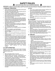
...; Keep all movement on a slope. any oil or fuel spillage before turning. SLOPE OPERATION • Never tamper with manufacturer's recommended parts, • Follow the manufacturer's recommendations for traffic when operating near drop-offs, ditches, or embankments. accidents, which could cause •... up . Allow machine to operate the machine. • Watch for wheel when necessary. Tall grass can touch hot exhaust / engine parts and burn. - and replace with safety devices. instructions, to occur. sliding. the ground. • Do not mow in reverse ...
...; Keep all movement on a slope. any oil or fuel spillage before turning. SLOPE OPERATION • Never tamper with manufacturer's recommended parts, • Follow the manufacturer's recommendations for traffic when operating near drop-offs, ditches, or embankments. accidents, which could cause •... up . Allow machine to operate the machine. • Watch for wheel when necessary. Tall grass can touch hot exhaust / engine parts and burn. - and replace with safety devices. instructions, to occur. sliding. the ground. • Do not mow in reverse ...
User Manual
Page 3
..., ruts, or bumps. Too heavy of your tractor. TABLE OF CONTENTS SAFETY RULES 2-3 STORAGE 24 PRODUCT SPECIFICATIONS 4 TROUBLESHOOTING 25-26 CUSTOMER RESPONSIBILITIES 4, 14-18 REPAIR PARTS 28-43 ASSEMBLY 6-8 WARRANTY 45 OPERATION 9-13 MAINTENANCE SCHEDULE 14 SERVICE AND ADJUSTMENTS 19-23 3 Stop machine if anyone enters the area. • Never carry...
..., ruts, or bumps. Too heavy of your tractor. TABLE OF CONTENTS SAFETY RULES 2-3 STORAGE 24 PRODUCT SPECIFICATIONS 4 TROUBLESHOOTING 25-26 CUSTOMER RESPONSIBILITIES 4, 14-18 REPAIR PARTS 28-43 ASSEMBLY 6-8 WARRANTY 45 OPERATION 9-13 MAINTENANCE SCHEDULE 14 SERVICE AND ADJUSTMENTS 19-23 3 Stop machine if anyone enters the area. • Never carry...
User Manual
Page 4
... local or state laws (if any problem you experience any ). Should you cannot easily remedy, please contact your nearest authorized service center/department (See REPAIR PARTS section of a new tractor. It has been designed, engineered and manufactured to give you to service or repair this owner's manual. We have competent, well...
... local or state laws (if any problem you experience any ). Should you cannot easily remedy, please contact your nearest authorized service center/department (See REPAIR PARTS section of a new tractor. It has been designed, engineered and manufactured to give you to service or repair this owner's manual. We have competent, well...
User Manual
Page 5
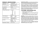
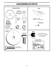
UNASSEMBLED PARTS Steering Wheel Steering Wheel Adapter Seat Steering Extension Shaft Steering Wheel Insert Steering Boot (1) Large Flat Washer (1) Lockwasher 3/8 (1) Locknut 5/16-18 (1) Hex Bolt 3/8-16 x 1 (1) Washer 17/32 x 1-3/16 x 12 Gauge (1) Lock Washer 1/2 (1) Bolt Keys (1) Oil Drain Tube For Future Use (2) Keys Slope Sheet (1) Hex Bolt 5/16-18 x 1-1/4 5
UNASSEMBLED PARTS Steering Wheel Steering Wheel Adapter Seat Steering Extension Shaft Steering Wheel Insert Steering Boot (1) Large Flat Washer (1) Lockwasher 3/8 (1) Locknut 5/16-18 (1) Hex Bolt 3/8-16 x 1 (1) Washer 17/32 x 1-3/16 x 12 Gauge (1) Lock Washer 1/2 (1) Bolt Keys (1) Oil Drain Tube For Future Use (2) Keys Slope Sheet (1) Hex Bolt 5/16-18 x 1-1/4 5
User Manual
Page 6
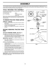
... securely. ASSEMBLY Your new tractor has been assembled at the factory with exception of those parts left unassembled for any additional loose parts or cartons and remove. To ensure safe and proper operation of your tractor all parts and hardware you are horizontal (left to right) and slide inside boot and onto adapter... securely. • Snap steering wheel insert into center of steering wheel. • Remove protective materials from top to bottom, along lines on all accessible loose parts and parts cartons from carton. • Cut, from tractor hood and grill.
... securely. ASSEMBLY Your new tractor has been assembled at the factory with exception of those parts left unassembled for any additional loose parts or cartons and remove. To ensure safe and proper operation of your tractor all parts and hardware you are horizontal (left to right) and slide inside boot and onto adapter... securely. • Snap steering wheel insert into center of steering wheel. • Remove protective materials from top to bottom, along lines on all accessible loose parts and parts cartons from carton. • Cut, from tractor hood and grill.
User Manual
Page 8
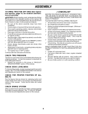
... of this manual. All assembly instructions have been completed. • Check engine oil level and fill fuel tank with all belt keepers. ! No remaining loose parts in the Operation section of other people and objects. • Be sure all the above assembly steps have been completed. ! Seat is properly leveled side...
... of this manual. All assembly instructions have been completed. • Check engine oil level and fill fuel tank with all belt keepers. ! No remaining loose parts in the Operation section of other people and objects. • Be sure all the above assembly steps have been completed. ! Seat is properly leveled side...
User Manual
Page 15
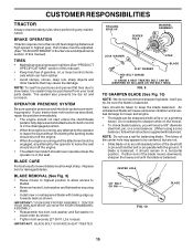
...; Remove hex bolt, lock washer and flat washer securing blade. • Install new or resharpened blade with a file or on a grinding wheel. If your local parts dealer. IMPORTANT: TO ENSURE PROPER ASSEMBLY, CENTER HOLE IN BLADE MUST ALIGN WITH STAR ON MANDREL ASSEMBLY. • Reassemble hex bolt, lock washer and flat...
...; Remove hex bolt, lock washer and flat washer securing blade. • Install new or resharpened blade with a file or on a grinding wheel. If your local parts dealer. IMPORTANT: TO ENSURE PROPER ASSEMBLY, CENTER HOLE IN BLADE MUST ALIGN WITH STAR ON MANDREL ASSEMBLY. • Reassemble hex bolt, lock washer and flat...
User Manual
Page 19
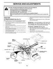
moving parts have completely stopped. • Disconnect spark plug wire from spark plug and place wire where it cannot come in contact with discharge guard to right ...
moving parts have completely stopped. • Disconnect spark plug wire from spark plug and place wire where it cannot come in contact with discharge guard to right ...
User Manual
Page 21
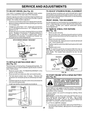
.... Do not lose). • Repair tire and reassemble. • On rear wheels only: align grooves in the Customer Responsibilities section of tractor. If your local parts dealer. ENGINE PULLEY CLUTCHING IDLER STATIONARY IDLER TRANSAXLE PULLEY AXLE COVER SQUARE KEY (REAR WHEEL ONLY) FIG. 24 TO START ENGINE WITH A WEAK BATTERY (See...
.... Do not lose). • Repair tire and reassemble. • On rear wheels only: align grooves in the Customer Responsibilities section of tractor. If your local parts dealer. ENGINE PULLEY CLUTCHING IDLER STATIONARY IDLER TRANSAXLE PULLEY AXLE COVER SQUARE KEY (REAR WHEEL ONLY) FIG. 24 TO START ENGINE WITH A WEAK BATTERY (See...
User Manual
Page 22
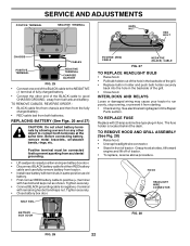
... the hole in the backside of the grill. • Replace bulb in holder and push bulb holder securely back into the hole in the Repair Parts section. HOOD HEADLIGHT WIRE CONNECTOR BATTERY BOX DOOR FIG. 28 FIG. 26 22
... the hole in the backside of the grill. • Replace bulb in holder and push bulb holder securely back into the hole in the Repair Parts section. HOOD HEADLIGHT WIRE CONNECTOR BATTERY BOX DOOR FIG. 28 FIG. 26 22
User Manual
Page 24
...corrosion and power leakage during storage. ENGINE FUEL SYSTEM IMPORTANT: IT IS IMPORTANT TO PREVENT GUM DEPOSITS FROM FORMING IN ESSENTIAL FUEL SYSTEM PARTS SUCH AS CARBURETOR, FUEL FILTER, FUEL HOSE, OR TANK DURING STORAGE. STORAGE Immediately prepare your tractor for storage at least 10 minutes... after adding stabilizer to allow the stabilizer to cool before painting. Allow the engine to reach the carburetor. Inspect moving parts for 30 days or more. ACIDIC GAS CAN DAMAGE THE FUEL SYSTEM OF AN ENGINE WHILE IN STORAGE. • Drain the fuel ...
...corrosion and power leakage during storage. ENGINE FUEL SYSTEM IMPORTANT: IT IS IMPORTANT TO PREVENT GUM DEPOSITS FROM FORMING IN ESSENTIAL FUEL SYSTEM PARTS SUCH AS CARBURETOR, FUEL FILTER, FUEL HOSE, OR TANK DURING STORAGE. STORAGE Immediately prepare your tractor for storage at least 10 minutes... after adding stabilizer to allow the stabilizer to cool before painting. Allow the engine to reach the carburetor. Inspect moving parts for 30 days or more. ACIDIC GAS CAN DAMAGE THE FUEL SYSTEM OF AN ENGINE WHILE IN STORAGE. • Drain the fuel ...
User Manual
Page 25
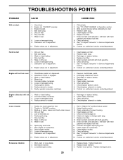
... Loose or damaged wiring. 14. Adjust throttle control. 3. Clean engine air screen/fins. 12. Tighten blade bolt. 2. Replace damaged parts. Engine flooded. 4. Carburetor out of adjustment. 8. Hard to start 1. Recharge or replace battery. 4. Contact an authorized service center/department.... 6. Carburetor out of adjustment. 1. Set in Service Adjustments section. 8. Connect and tighten spark plug wire. 11. Tighten loose part(s). Bad spark plug. 3. Engine valves out of adjustment. 15. Engine will not start 1. Replace fuse. 5. Faulty solenoid or ...
... Loose or damaged wiring. 14. Adjust throttle control. 3. Clean engine air screen/fins. 12. Tighten blade bolt. 2. Replace damaged parts. Engine flooded. 4. Carburetor out of adjustment. 8. Hard to start 1. Recharge or replace battery. 4. Contact an authorized service center/department.... 6. Carburetor out of adjustment. 1. Set in Service Adjustments section. 8. Connect and tighten spark plug wire. 11. Tighten loose part(s). Bad spark plug. 3. Engine valves out of adjustment. 15. Engine will not start 1. Replace fuse. 5. Faulty solenoid or ...
User Manual
Page 29
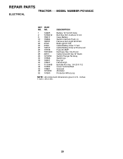
... - - inches 1 inch = 25.4 mm. 29 MODEL NUMBER PO14542C ELECTRICAL KEY PART NO. NO. 1 144925 2 74760412 8 156417 16 153664 21 166181 22 4152J 24 4799J 25 146147 26 175158 27 73510400 28 4207J 29 121305X 30 175566 ...
... - - inches 1 inch = 25.4 mm. 29 MODEL NUMBER PO14542C ELECTRICAL KEY PART NO. NO. 1 144925 2 74760412 8 156417 16 153664 21 166181 22 4152J 24 4799J 25 146147 26 175158 27 73510400 28 4207J 29 121305X 30 175566 ...
User Manual
Page 31
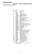
... - - MODEL NUMBER PO14542C CHASSIS AND ENCLOSURES KEY PART NO. Dash Lh 12 145660 Clip Tinnerman Grile P/L 13 172107X010 Panel Dash Rh 15 74180512 Screw Mach Trhd 5/16-18 Unc x 3/4 16 73510500 Nut Keps 5/...
... - - MODEL NUMBER PO14542C CHASSIS AND ENCLOSURES KEY PART NO. Dash Lh 12 145660 Clip Tinnerman Grile P/L 13 172107X010 Panel Dash Rh 15 74180512 Screw Mach Trhd 5/16-18 Unc x 3/4 16 73510500 Nut Keps 5/...
User Manual
Page 33
... 36 19211616 37 1572H 38 165936 39 74760648 40 175461 41 175556 42 19131312 47 127783 48 154407 DESCRIPTION Transaxle Peerless Model 206-545C (Order Parts From Transaxle Manufacturer) Spring Extension Brake Pulley Transaxle 18" tires Ring Retainer # 5100-62 Strap Torque Rh Pnt Blk Screw 5/16-18 X 3/4 Bracket T/A ...Bolt Fin Hex 3/8-16 Unc x 3 Spacer Split Keeper Belt Idler Washer 13/32 X 13/16 X 12 Ga Pulley Idler V Groove Plastic Bellcrank Clutch KEY PART NO. inches 1 inch = 25.4 mm 33 NO. 49 123205X 50 74760624 51 73680600 52 73680500 53 105710X 55 105709X 56 17060616 57 130801 59 169691...
... 36 19211616 37 1572H 38 165936 39 74760648 40 175461 41 175556 42 19131312 47 127783 48 154407 DESCRIPTION Transaxle Peerless Model 206-545C (Order Parts From Transaxle Manufacturer) Spring Extension Brake Pulley Transaxle 18" tires Ring Retainer # 5100-62 Strap Torque Rh Pnt Blk Screw 5/16-18 X 3/4 Bracket T/A ...Bolt Fin Hex 3/8-16 Unc x 3 Spacer Split Keeper Belt Idler Washer 13/32 X 13/16 X 12 Ga Pulley Idler V Groove Plastic Bellcrank Clutch KEY PART NO. inches 1 inch = 25.4 mm 33 NO. 49 123205X 50 74760624 51 73680600 52 73680500 53 105710X 55 105709X 56 17060616 57 130801 59 169691...
User Manual
Page 34
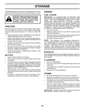
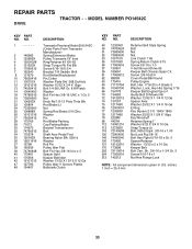
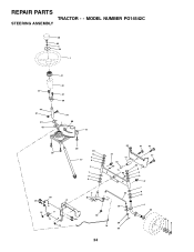
MODEL NUMBER PO14542C STEERING ASSEMBLY 38 63 11 39 1 37 44 51 91 43 41 42 37 36 54 88 71 29 68 29 82 15 15 15 29 46 8 6 17 9 2 7 9 5 3 40 29 68 67 67 47 13 65 85 85 32 11 26 67 46 8 6 9 47 7 9 5 4 43 28 10 30 34 43 6 8 REPAIR PARTS TRACTOR - -
MODEL NUMBER PO14542C STEERING ASSEMBLY 38 63 11 39 1 37 44 51 91 43 41 42 37 36 54 88 71 29 68 29 82 15 15 15 29 46 8 6 17 9 2 7 9 5 3 40 29 68 67 67 47 13 65 85 85 32 11 26 67 46 8 6 9 47 7 9 5 4 43 28 10 30 34 43 6 8 REPAIR PARTS TRACTOR - -
User Manual
Page 35
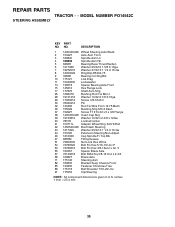
inches 1 inch = 25.4 mm 35 NO. MODEL NUMBER PO14542C STEERING ASSEMBLY KEY PART NO. REPAIR PARTS TRACTOR - - DESCRIPTION 1 140044X428 Wheel Steering Auto Black 2 154427 Axle Asm Front 3 169840 Spindle Asm Lh 4 169839 Spindle Asm Rh 5 6266H Bearing Race Thrust Harden 6 121748X ...
inches 1 inch = 25.4 mm 35 NO. MODEL NUMBER PO14542C STEERING ASSEMBLY KEY PART NO. REPAIR PARTS TRACTOR - - DESCRIPTION 1 140044X428 Wheel Steering Auto Black 2 154427 Axle Asm Front 3 169840 Spindle Asm Lh 4 169839 Spindle Asm Rh 5 6266H Bearing Race Thrust Harden 6 121748X ...
User Manual
Page 37
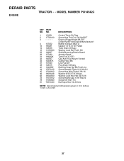
... 17000612 46 19091416 62 10040500 72 71070512 78 17060620 81 73510400 Control Throt /Ch Flag Screw Hex Thd Cut 1/4-20x5/8 T Engine Briggs Model 28U707 (Order Parts From Engine Manufacturer) Muffler Exhaust B&S Lt Gasket 1 313 Id Tin Plated Tube Drain Oil Easy Washer Lock Ext Tooth 3/8 Shield Browning/Debris Guard Arrestor Spark... 5/16-18x3/4 Screw 3/8-16x1-1/4 Nut Keps Hex 1/4-20 Unc NOTE: All component dimensions given in U.S. inches 1 inch = 25.4 mm 37 MODEL NUMBER PO14542C ENGINE KEY PART NO. REPAIR PARTS TRACTOR - -
... 17000612 46 19091416 62 10040500 72 71070512 78 17060620 81 73510400 Control Throt /Ch Flag Screw Hex Thd Cut 1/4-20x5/8 T Engine Briggs Model 28U707 (Order Parts From Engine Manufacturer) Muffler Exhaust B&S Lt Gasket 1 313 Id Tin Plated Tube Drain Oil Easy Washer Lock Ext Tooth 3/8 Shield Browning/Debris Guard Arrestor Spark... 5/16-18x3/4 Screw 3/8-16x1-1/4 Nut Keps Hex 1/4-20 Unc NOTE: All component dimensions given in U.S. inches 1 inch = 25.4 mm 37 MODEL NUMBER PO14542C ENGINE KEY PART NO. REPAIR PARTS TRACTOR - -
User Manual
Page 38
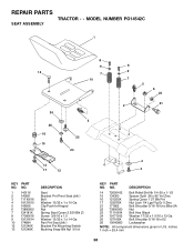
... Blk Zi Screw 3/8-16 x 1.5 Washer 13/32 x 1 x 14 Ga Pan Pnt Seat (blk ) Bracket Pnt Mounting Switch Bushing Snap Blk Nyl 50 Id KEY PART NO. REPAIR PARTS TRACTOR - - DESCRIPTION 14 72050412 15 134300 16 121250X 17 123976X 21 171852 22 73800500 23 71110814 24 19171912 25 127018X 26 10040800 Bolt Rdhd... NOTE: All component dimensions given in U.S. MODEL NUMBER PO14542C SEAT ASSEMBLY 1 8 9 14 7 10 24 26 16 15 5 25 23 13 17 12 8 9 7 2 5 6 22 21 4 3 KEY PART NO. NO. inches 1 inch = 25.4 mm 38
... Blk Zi Screw 3/8-16 x 1.5 Washer 13/32 x 1 x 14 Ga Pan Pnt Seat (blk ) Bracket Pnt Mounting Switch Bushing Snap Blk Nyl 50 Id KEY PART NO. REPAIR PARTS TRACTOR - - DESCRIPTION 14 72050412 15 134300 16 121250X 17 123976X 21 171852 22 73800500 23 71110814 24 19171912 25 127018X 26 10040800 Bolt Rdhd... NOTE: All component dimensions given in U.S. MODEL NUMBER PO14542C SEAT ASSEMBLY 1 8 9 14 7 10 24 26 16 15 5 25 23 13 17 12 8 9 7 2 5 6 22 21 4 3 KEY PART NO. NO. inches 1 inch = 25.4 mm 38


