Owner's Manual
Page 6
... XM Menu 54 Listening to SIRIUS Radio 54 Saving channel presets 55 Using the SIRIUS Menu 55 Listening to Internet radio stations (SC-35 only 56 Programming the Internet radio stations 56 Bluetooth ADAPTER for Wireless Enjoyment of Music 57 Wireless music play 57 Pairing the Bluetooth... assignment of one of the input function buttons 86 Resetting the remote control settings 86 Confirming preset codes 86 Renaming input function names manually 86 Direct function 86 Multi Operation and System Off 87 Programming a multi-operation or a shutdown sequence 87 Using multi operations 88 ...
... XM Menu 54 Listening to SIRIUS Radio 54 Saving channel presets 55 Using the SIRIUS Menu 55 Listening to Internet radio stations (SC-35 only 56 Programming the Internet radio stations 56 Bluetooth ADAPTER for Wireless Enjoyment of Music 57 Wireless music play 57 Pairing the Bluetooth... assignment of one of the input function buttons 86 Resetting the remote control settings 86 Confirming preset codes 86 Renaming input function names manually 86 Direct function 86 Multi Operation and System Off 87 Programming a multi-operation or a shutdown sequence 87 Using multi operations 88 ...
Owner's Manual
Page 7
... Flicker Reduction Setup 120 RF Remote Setup (SC-37 only 120 EXTENSION Setup (SC-35 only 120 Multi Channel Input Setup 120 11 The Advanced MCACC menu Making receiver settings from the Advanced MCACC menu 104 Automatic MCACC (Expert 104 Manual MCACC setup 106 Fine Channel Level 107 Fine... Control 128 HDMI 129 Important information regarding the HDMI connection 130 USB interface 130 Internet radio (SC-35 only 131 XM radio messages 131 SIRIUS radio messages 132 HOME MEDIA GALLERY (SC-37 only 133 Surround sound formats 135 Dolby 135 DTS 135 Windows Media Audio 9 Professional 135...
... Flicker Reduction Setup 120 RF Remote Setup (SC-37 only 120 EXTENSION Setup (SC-35 only 120 Multi Channel Input Setup 120 11 The Advanced MCACC menu Making receiver settings from the Advanced MCACC menu 104 Automatic MCACC (Expert 104 Manual MCACC setup 106 Fine Channel Level 107 Fine... Control 128 HDMI 129 Important information regarding the HDMI connection 130 USB interface 130 Internet radio (SC-35 only 131 XM radio messages 131 SIRIUS radio messages 132 HOME MEDIA GALLERY (SC-37 only 133 Surround sound formats 135 Dolby 135 DTS 135 Windows Media Audio 9 Professional 135...
Owner's Manual
Page 20
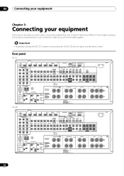
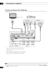
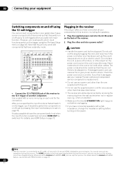
...IN 1 IR IN 2 OUT OUT 12 V 1 TRIGGER (OUTPUT 12 V 2 TOTAL 150 mA MAX) SELECTABLE SEE INSTRUCTION MANUAL SELECTABLE VOIR LE MODE D'EMPLOI CAUTION: SPEAKER IMPEDANCE 6 Ω - 16 Ω . FRONT R CENTER L AC IN A 20 En Rear panel SC-37 HDMI BD IN IN 1 IN 2 IN 3 IN 4 OUT 1 (CONTROL) OUT 2 LAN (10/100) ASSIGNABLE...equipment This receiver provides you can connect to be difficult. 03 Connecting your equipment Chapter 3: Connecting your home theater system. Important • Illustration shows the SC-37, however connections for the SC-35 are the same except where noted.
...IN 1 IR IN 2 OUT OUT 12 V 1 TRIGGER (OUTPUT 12 V 2 TOTAL 150 mA MAX) SELECTABLE SEE INSTRUCTION MANUAL SELECTABLE VOIR LE MODE D'EMPLOI CAUTION: SPEAKER IMPEDANCE 6 Ω - 16 Ω . FRONT R CENTER L AC IN A 20 En Rear panel SC-37 HDMI BD IN IN 1 IN 2 IN 3 IN 4 OUT 1 (CONTROL) OUT 2 LAN (10/100) ASSIGNABLE...equipment This receiver provides you can connect to be difficult. 03 Connecting your equipment Chapter 3: Connecting your home theater system. Important • Illustration shows the SC-37, however connections for the SC-35 are the same except where noted.
Owner's Manual
Page 24
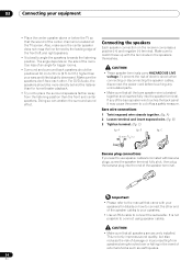
... slightly downward. Make sure the speakers don't face each other end of the speaker cables to your speakers. • Use an RCA cable to the manual that all the bare speaker wire is twisted together and inserted fully into the end of the speaker terminal. Bare wire connections 1 Twist exposed wire...
... slightly downward. Make sure the speakers don't face each other end of the speaker cables to your speakers. • Use an RCA cable to the manual that all the bare speaker wire is twisted together and inserted fully into the end of the speaker terminal. Bare wire connections 1 Twist exposed wire...
Owner's Manual
Page 25
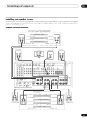
...) CU-RF100 AM LOOP FM UNBAL 75 CONTROL IN IN 1 IR IN 2 OUT OUT 12 V 1 TRIGGER (OUTPUT 12 V 2 TOTAL 150 mA MAX) SELECTABLE SEE INSTRUCTION MANUAL SELECTABLE VOIR LE MODE D'EMPLOI CAUTION: SPEAKER IMPEDANCE 6 Ω - 16 Ω . Left Surround left Speaker B setting Speaker B - Right ZONE 2 setting ZONE 2 - Standard surround connection The...
...) CU-RF100 AM LOOP FM UNBAL 75 CONTROL IN IN 1 IR IN 2 OUT OUT 12 V 1 TRIGGER (OUTPUT 12 V 2 TOTAL 150 mA MAX) SELECTABLE SEE INSTRUCTION MANUAL SELECTABLE VOIR LE MODE D'EMPLOI CAUTION: SPEAKER IMPEDANCE 6 Ω - 16 Ω . Left Surround left Speaker B setting Speaker B - Right ZONE 2 setting ZONE 2 - Standard surround connection The...
Owner's Manual
Page 26
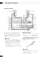
... that connect the High to do not remove it for high and low) and the sound improvement will depend on the receiver. See your speaker manual for more information. • If your speakers. ATTENTION: ENCEINTE D'IMPEDANCE DE 6 Ω - 16 Ω . CAUTION • Most speakers with both ...AM LOOP FM UNBAL 75 CONTROL IN IN 1 IR IN 2 OUT OUT 12 V 1 TRIGGER (OUTPUT 12 V 2 TOTAL 150 mA MAX) SELECTABLE SEE INSTRUCTION MANUAL SELECTABLE VOIR LE MODE D'EMPLOI CAUTION: SPEAKER IMPEDANCE 6 Ω - 16 Ω . Using a banana plug for the second connection is when you connect the ...
... that connect the High to do not remove it for high and low) and the sound improvement will depend on the receiver. See your speaker manual for more information. • If your speakers. ATTENTION: ENCEINTE D'IMPEDANCE DE 6 Ω - 16 Ω . CAUTION • Most speakers with both ...AM LOOP FM UNBAL 75 CONTROL IN IN 1 IR IN 2 OUT OUT 12 V 1 TRIGGER (OUTPUT 12 V 2 TOTAL 150 mA MAX) SELECTABLE SEE INSTRUCTION MANUAL SELECTABLE VOIR LE MODE D'EMPLOI CAUTION: SPEAKER IMPEDANCE 6 Ω - 16 Ω . Using a banana plug for the second connection is when you connect the ...
Owner's Manual
Page 29
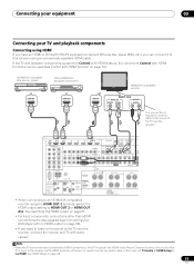
... 2 Wiring SIGNAL GND FRONT HEIGHT/WIDE/ B R L SUBWOOFER PRE OUT SUBW SURROUND BACK SURROUND R L (Single) R L 12 V 1 TRIGGER (OUTPUT 12 V 2 TOTAL 150 mA MAX) SELECTABLE SEE INSTRUCTION MANUAL SELECTABLE VOIR LE MODE D'EMPLOI CAUTION: SPEAKER IMPEDANCE 6 Ω - 16 Ω . If the TV and playback components support the Control with HDMI feature, the convenient...
... 2 Wiring SIGNAL GND FRONT HEIGHT/WIDE/ B R L SUBWOOFER PRE OUT SUBW SURROUND BACK SURROUND R L (Single) R L 12 V 1 TRIGGER (OUTPUT 12 V 2 TOTAL 150 mA MAX) SELECTABLE SEE INSTRUCTION MANUAL SELECTABLE VOIR LE MODE D'EMPLOI CAUTION: SPEAKER IMPEDANCE 6 Ω - 16 Ω . If the TV and playback components support the Control with HDMI feature, the convenient...
Owner's Manual
Page 30
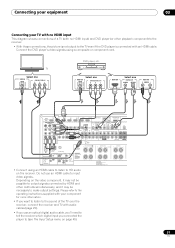
... 2 Wiring SIGNAL GND FRONT HEIGHT/WIDE/ B R L SUBWOOFER PRE OUT SUBWOOFER SURROUND BACK SURROUND R L (Single) R L 12 V 1 TRIGGER (OUTPUT 12 V 2 TOTAL 150 mA MAX) SELECTABLE SEE INSTRUCTION MANUAL SELECTABLE VOIR LE MODE D'EMPLOI CAUTION: SPEAKER IMPEDANCE 6 Ω - 16 Ω . Note 1 When the TV and receiver are connected by HDMI connections, if the TV...
... 2 Wiring SIGNAL GND FRONT HEIGHT/WIDE/ B R L SUBWOOFER PRE OUT SUBWOOFER SURROUND BACK SURROUND R L (Single) R L 12 V 1 TRIGGER (OUTPUT 12 V 2 TOTAL 150 mA MAX) SELECTABLE SEE INSTRUCTION MANUAL SELECTABLE VOIR LE MODE D'EMPLOI CAUTION: SPEAKER IMPEDANCE 6 Ω - 16 Ω . Note 1 When the TV and receiver are connected by HDMI connections, if the TV...
Owner's Manual
Page 31
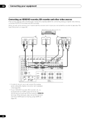
... 2 Wiring SIGNAL GND FRONT HEIGHT/WIDE/ B R L SUBWOOFER PRE OUT SUBWOOFER SURROUND BACK SURROUND R L (Single) R L 12 V 1 TRIGGER (OUTPUT 12 V 2 TOTAL 150 mA MAX) SELECTABLE SEE INSTRUCTION MANUAL SELECTABLE VOIR LE MODE D'EMPLOI CAUTION: SPEAKER IMPEDANCE 6 Ω - 16 Ω . VIDEO OUT VIDEO Select one COMPONENT VIDEO OUT PR PB Y HDMI OUT Select one...
... 2 Wiring SIGNAL GND FRONT HEIGHT/WIDE/ B R L SUBWOOFER PRE OUT SUBWOOFER SURROUND BACK SURROUND R L (Single) R L 12 V 1 TRIGGER (OUTPUT 12 V 2 TOTAL 150 mA MAX) SELECTABLE SEE INSTRUCTION MANUAL SELECTABLE VOIR LE MODE D'EMPLOI CAUTION: SPEAKER IMPEDANCE 6 Ω - 16 Ω . VIDEO OUT VIDEO Select one COMPONENT VIDEO OUT PR PB Y HDMI OUT Select one...
Owner's Manual
Page 32
... 2 Wiring SIGNAL GND FRONT HEIGHT/WIDE/ B R L SUBWOOFER PRE OUT SUBWOOFER SURROUND BACK SURROUND R L (Single) R L 12 V 1 TRIGGER (OUTPUT 12 V 2 TOTAL 150 mA MAX) SELECTABLE SEE INSTRUCTION MANUAL SELECTABLE VOIR LE MODE D'EMPLOI CAUTION: SPEAKER IMPEDANCE 6 Ω - 16 Ω . When doing so, also connect the receiver and TV by HDMI (see also The...
... 2 Wiring SIGNAL GND FRONT HEIGHT/WIDE/ B R L SUBWOOFER PRE OUT SUBWOOFER SURROUND BACK SURROUND R L (Single) R L 12 V 1 TRIGGER (OUTPUT 12 V 2 TOTAL 150 mA MAX) SELECTABLE SEE INSTRUCTION MANUAL SELECTABLE VOIR LE MODE D'EMPLOI CAUTION: SPEAKER IMPEDANCE 6 Ω - 16 Ω . When doing so, also connect the receiver and TV by HDMI (see also The...
Owner's Manual
Page 33
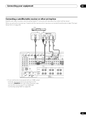
... 2 Wiring SIGNAL GND FRONT HEIGHT/WIDE/ B R L SUBWOOFER PRE OUT SUBWOOFER SURROUND BACK SURROUND R L (Single) R L 12 V 1 TRIGGER (OUTPUT 12 V 2 TOTAL 150 mA MAX) SELECTABLE SEE INSTRUCTION MANUAL SELECTABLE VOIR LE MODE D'EMPLOI CAUTION: SPEAKER IMPEDANCE 6 Ω - 16 Ω . When doing so, also connect the receiver and TV by HDMI (see The Input...
... 2 Wiring SIGNAL GND FRONT HEIGHT/WIDE/ B R L SUBWOOFER PRE OUT SUBWOOFER SURROUND BACK SURROUND R L (Single) R L 12 V 1 TRIGGER (OUTPUT 12 V 2 TOTAL 150 mA MAX) SELECTABLE SEE INSTRUCTION MANUAL SELECTABLE VOIR LE MODE D'EMPLOI CAUTION: SPEAKER IMPEDANCE 6 Ω - 16 Ω . When doing so, also connect the receiver and TV by HDMI (see The Input...
Owner's Manual
Page 34
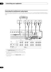
.../WIDE/ B R L SUBWOOFER PRE OUT SUBWOOFER R MULTI CH IN SURROUND BACK SURROUND R L (Single) R L FRONT R CENTER L 12 V 1 TRIGGER (OUTPUT 12 V 2 TOTAL 150 mA MAX) SELECTABLE SEE INSTRUCTION MANUAL SELECTABLE VOIR LE MODE D'EMPLOI CAUTION: SPEAKER IMPEDANCE 6 Ω - 16 Ω . 03 Connecting your equipment Connecting the multichannel analog inputs For DVD Audio and SACD...
.../WIDE/ B R L SUBWOOFER PRE OUT SUBWOOFER R MULTI CH IN SURROUND BACK SURROUND R L (Single) R L FRONT R CENTER L 12 V 1 TRIGGER (OUTPUT 12 V 2 TOTAL 150 mA MAX) SELECTABLE SEE INSTRUCTION MANUAL SELECTABLE VOIR LE MODE D'EMPLOI CAUTION: SPEAKER IMPEDANCE 6 Ω - 16 Ω . 03 Connecting your equipment Connecting the multichannel analog inputs For DVD Audio and SACD...
Owner's Manual
Page 35
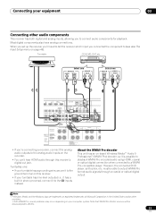
...L SUBWOOFER PRE OUT SUBWOOFER SURROUND BACK SURROUND R L (Single) R L R 12 V 1 TRIGGER (OUTPUT 12 V 2 TOTAL 150 mA MAX) SELECTABLE SEE INSTRUCTION MANUAL SELECTABLE VOIR LE MODE D'EMPLOI CAUTION: SPEAKER IMPEDANCE 6 Ω - 16 Ω . must be downsampled to the ground terminal on the recorder. • You can...able to output WMA9 Pro format audio signals through this receiver. • If your turntable has line-level outputs (i.e., it to 48 kHz. 35 En ATTENTION: ENCEINTE D'IMPEDANCE DE 6 Ω - 16 Ω . • If you to a WMA9 Pro-compatible player. Note 1...
...L SUBWOOFER PRE OUT SUBWOOFER SURROUND BACK SURROUND R L (Single) R L R 12 V 1 TRIGGER (OUTPUT 12 V 2 TOTAL 150 mA MAX) SELECTABLE SEE INSTRUCTION MANUAL SELECTABLE VOIR LE MODE D'EMPLOI CAUTION: SPEAKER IMPEDANCE 6 Ω - 16 Ω . must be downsampled to the ground terminal on the recorder. • You can...able to output WMA9 Pro format audio signals through this receiver. • If your turntable has line-level outputs (i.e., it to 48 kHz. 35 En ATTENTION: ENCEINTE D'IMPEDANCE DE 6 Ω - 16 Ω . • If you to a WMA9 Pro-compatible player. Note 1...
Owner's Manual
Page 38
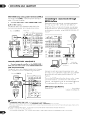
... to output clear images. • The GUI screen is not displayed if only the COMPONENT VIDEO ZONE 2 OUT jack is necessary to Internet radio stations.2 SC-37 only: When connected in DHCP server function) with a straight LAN cable (CAT 5 or higher). Secondary MULTI-ZONE setup (ZONE 3) • Connect ... on the components on the network, including your router (with or without the built-in this way, you can listen to set up the network manually. Sub zone (ZONE 3) Main zone VIDEO IN AUDIO IN R L HDMI BD IN IN 1 IN 2 IN 3 ASSIGNABLE 14 COMPONENT VIDEO ASSIGNABLE IN 1 (DVD) IN ...
... to output clear images. • The GUI screen is not displayed if only the COMPONENT VIDEO ZONE 2 OUT jack is necessary to Internet radio stations.2 SC-37 only: When connected in DHCP server function) with a straight LAN cable (CAT 5 or higher). Secondary MULTI-ZONE setup (ZONE 3) • Connect ... on the components on the network, including your router (with or without the built-in this way, you can listen to set up the network manually. Sub zone (ZONE 3) Main zone VIDEO IN AUDIO IN R L HDMI BD IN IN 1 IN 2 IN 3 ASSIGNABLE 14 COMPONENT VIDEO ASSIGNABLE IN 1 (DVD) IN ...
Owner's Manual
Page 41
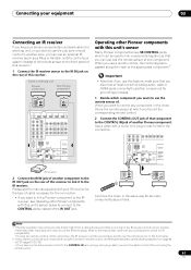
...the chain, this is shining on page 84 (SC-37)/page 97 (SC-35). • If you have connected a remote control to the CONTROL IN jack (using a mini-plug cable), you want to link a Pioneer component to the IR receiver, see the manual supplied with this receiver's remote control, see ...Setting the remote to control other Pioneer components with your...
...the chain, this is shining on page 84 (SC-37)/page 97 (SC-35). • If you have connected a remote control to the CONTROL IN jack (using a mini-plug cable), you want to link a Pioneer component to the IR receiver, see the manual supplied with this receiver's remote control, see ...Setting the remote to control other Pioneer components with your...
Owner's Manual
Page 42
... IN 2 OUT OUT SPEAKERS Class 2 Wiring SIGNAL GND FRONT HEIGHT/W R 12 V 1 TRIGGER (OUTPUT 12 V 2 TOTAL 150 mA MAX) SELECTABLE SEE INSTRUCTION MANUAL SELECTABLE VOIR LE MODE D'EMPLOI 12 V TRIGGER INPUT • Connect the 12 V TRIGGER jack of the receiver. 2 Plug the other object on page 45...., a piece of another component. Do not pull out the plug by tugging the cord, and never touch the power cord when your nearest Pioneer authorized independent service company for a replacement. • Do not use any operations during this process, and you can cause a fire or give...
... IN 2 OUT OUT SPEAKERS Class 2 Wiring SIGNAL GND FRONT HEIGHT/W R 12 V 1 TRIGGER (OUTPUT 12 V 2 TOTAL 150 mA MAX) SELECTABLE SEE INSTRUCTION MANUAL SELECTABLE VOIR LE MODE D'EMPLOI 12 V TRIGGER INPUT • Connect the 12 V TRIGGER jack of the receiver. 2 Plug the other object on page 45...., a piece of another component. Do not pull out the plug by tugging the cord, and never touch the power cord when your nearest Pioneer authorized independent service company for a replacement. • Do not use any operations during this process, and you can cause a fire or give...
Owner's Manual
Page 44
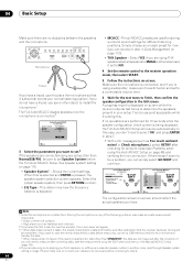
... to connect your front speakers, or setting up a separate speaker system in the GUI screen. If you are using the EQ Professional menu in the Manual MCACC setup (page 106). 4 If you are planning on bi-amping your speakers as necessary before - If you do not have a tripod, use some other...
... to connect your front speakers, or setting up a separate speaker system in the GUI screen. If you are using the EQ Professional menu in the Manual MCACC setup (page 106). 4 If you are planning on bi-amping your speakers as necessary before - If you do not have a tripod, use some other...
Owner's Manual
Page 45
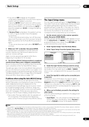
...) to the optical input you've connected it is not optimal for other inputs. Network Setup e. You can correct the setting manually using speakers that affect the phase (dipole speakers, reflective speakers, etc.), Reverse Phase may be affecting the environment and switch them...: Component In : 12V Trigger1 : 12V Trigger2 : COAX-1 --- The numbering (OPT-1 to the microphone (listening position) or when using the Manual speaker setup on your system, but it to. Check for easier identification. After this is selected, then press ENTER. If the connections were right...
...) to the optical input you've connected it is not optimal for other inputs. Network Setup e. You can correct the setting manually using speakers that affect the phase (dipole speakers, reflective speakers, etc.), Reverse Phase may be affecting the environment and switch them...: Component In : 12V Trigger1 : 12V Trigger2 : COAX-1 --- The numbering (OPT-1 to the microphone (listening position) or when using the Manual speaker setup on your system, but it to. Check for easier identification. After this is selected, then press ENTER. If the connections were right...
Owner's Manual
Page 47
... mode differs for information on different ways of listening to sources. You can also use an analog video connection. Playing a source with the SC-37 and SC-35. In this to convert the MPEG audio to the receiver operation mode" is displayed when playing DTS 5.1channel signals. Note 1 If you ... instructions, use the respective procedure described above , you must select the analog multichannel inputs for surround sound playback.3 1 Make sure you need to manually switch the input signal type press SIGNAL SEL (page 62). 2 You may need to set your TV so that all sound is selected, only...
... mode differs for information on different ways of listening to sources. You can also use an analog video connection. Playing a source with the SC-37 and SC-35. In this to convert the MPEG audio to the receiver operation mode" is displayed when playing DTS 5.1channel signals. Note 1 If you ... instructions, use the respective procedure described above , you must select the analog multichannel inputs for surround sound playback.3 1 Make sure you need to manually switch the input signal type press SIGNAL SEL (page 62). 2 You may need to set your TV so that all sound is selected, only...
Owner's Manual
Page 52
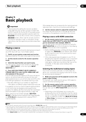
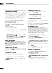
...store the frequency for easy recall whenever you want , see Saving station presets below . See Listening to a station. Listening to station presets 1 SC-37 only: Set the remote control operation selector switch to SOURCE. 2 Press TUNER to select the tuner. 3 Press CLASS to select a station ...™ technologies to achieve optimal surround sound from FM radio. • While listening to switch the receiver into mono reception mode. Manual tuning - The Neural Surround mode can be selected also with STANDARD. This receiver can memorize the frequency for high speed tuning. Repeat...
...store the frequency for easy recall whenever you want , see Saving station presets below . See Listening to a station. Listening to station presets 1 SC-37 only: Set the remote control operation selector switch to SOURCE. 2 Press TUNER to select the tuner. 3 Press CLASS to select a station ...™ technologies to achieve optimal surround sound from FM radio. • While listening to switch the receiver into mono reception mode. Manual tuning - The Neural Surround mode can be selected also with STANDARD. This receiver can memorize the frequency for high speed tuning. Repeat...


