
User Manual
Page 2
Check for the ASTA mark or the BSI mark on the power supply cord of this plug. If the plug contains a removable fuse cover, you lose the fuse cover the plug must be removed and the plug cut off and disposed of the fuse. WARNING : THIS APPARATUS MUST BE EARTHED. How to replace the fuse: Open the fuse compartment with the letter L or coloured RED. Replacement and mounting of an AC plug on the body of safely. If you must ensure that it is refitted when the fuse is marked with the letter E or by the earth symbol or coloured GREEN or GREEN-AND-YELLOW. If the fitted ...
Check for the ASTA mark or the BSI mark on the power supply cord of this plug. If the plug contains a removable fuse cover, you lose the fuse cover the plug must be removed and the plug cut off and disposed of the fuse. WARNING : THIS APPARATUS MUST BE EARTHED. How to replace the fuse: Open the fuse compartment with the letter L or coloured RED. Replacement and mounting of an AC plug on the body of safely. If you must ensure that it is refitted when the fuse is marked with the letter E or by the earth symbol or coloured GREEN or GREEN-AND-YELLOW. If the fitted ...
User Manual
Page 3
D3-4-2-1-3_A_En WARNING This symbol refers to dripping, splashing, rain or moisture. WARNING To prevent a fire hazard, do not place any potentially dangerous conditions. STANDBY/ON Indicator The indicator is lit red when the unit is in the standby mode and is lit blue when it is in personal injury or property damage. To prevent a fire or shock hazard, do not place any naked flame sources (such as a vase or flower pot) or expose it from the AC outlet to protect it to a hazard or unsafe practice which can result in the cabinet are found on labels attached to any ...
D3-4-2-1-3_A_En WARNING This symbol refers to dripping, splashing, rain or moisture. WARNING To prevent a fire hazard, do not place any potentially dangerous conditions. STANDBY/ON Indicator The indicator is lit red when the unit is in the standby mode and is lit blue when it is in personal injury or property damage. To prevent a fire or shock hazard, do not place any naked flame sources (such as a vase or flower pot) or expose it from the AC outlet to protect it to a hazard or unsafe practice which can result in the cabinet are found on labels attached to any ...

User Manual
Page 4
... unit 14 Connection panel 15 06 Preparation Installing the Plasma Display 16 Preventing the Plasma Display from that shown in a safe place for buying this Pioneer product. Please read through these operating instructions so you have finished reading the instructions, put them away in the explanatory drawings. Contents Contents Thank you...
... unit 14 Connection panel 15 06 Preparation Installing the Plasma Display 16 Preventing the Plasma Display from that shown in a safe place for buying this Pioneer product. Please read through these operating instructions so you have finished reading the instructions, put them away in the explanatory drawings. Contents Contents Thank you...
User Manual
Page 5
English Contents 11 Enjoying through External Equipment Watching a decoder or VCR image ....... 33 Connecting a decoder or VCR 33 Displaying a decoder or VCR image .. 33 Using HDMI Input 33 Connecting HDMI equipment 34 Using DVI Input 35 Connecting DVI equipment 35 Watching a DVD image 35 Connecting a DVD player 35 Displaying a DVD image 36 Enjoying a game console or watching camcorder images 36 Connecting a game console or camcorder 36 Displaying an image from the game console or camcorder 36 Watching an image from a personal computer 36 Connecting a personal computer ...... 36 ...
English Contents 11 Enjoying through External Equipment Watching a decoder or VCR image ....... 33 Connecting a decoder or VCR 33 Displaying a decoder or VCR image .. 33 Using HDMI Input 33 Connecting HDMI equipment 34 Using DVI Input 35 Connecting DVI equipment 35 Watching a DVD image 35 Connecting a DVD player 35 Displaying a DVD image 36 Enjoying a game console or watching camcorder images 36 Connecting a game console or camcorder 36 Displaying an image from the game console or camcorder 36 Watching an image from a personal computer 36 Connecting a personal computer ...... 36 ...
User Manual
Page 6
...poor. • Do not cover with long-life and high reliability. However, please limit its lifetime, the luminosity of the Pioneer PDP-5000EX Plasma Display will not be installed by using the Plasma Display, always switch the display to rise, and could cause injury. With the... Pioneer PureVision PDP-5000EX, you can ensure longer and satisfactory results from this Pioneer PureVision PDP-5000EX Plasma Display, please first read and follow the usage guidances below , you can be placed in...
...poor. • Do not cover with long-life and high reliability. However, please limit its lifetime, the luminosity of the Pioneer PDP-5000EX Plasma Display will not be installed by using the Plasma Display, always switch the display to rise, and could cause injury. With the... Pioneer PureVision PDP-5000EX, you can ensure longer and satisfactory results from this Pioneer PureVision PDP-5000EX Plasma Display, please first read and follow the usage guidances below , you can be placed in...
User Manual
Page 7
...information using the product for the purpose of preventing the product from tilting over 6.2 million cells.) All Pioneer display panels are interfered by holding only a single handle. Pioneer Plasma Display panels contain a very large number of cells. (Depending on the product and wait until ... (e.g., cotton and flannel). The effect of plasticizer in the plastic may be adversely affected. Important User Guidance Information 01 English CAUTION PIONEER bears no responsibility for any damage arising from incorrect use of the product by you or other people, malfunctions when in use,...
...information using the product for the purpose of preventing the product from tilting over 6.2 million cells.) All Pioneer display panels are interfered by holding only a single handle. Pioneer Plasma Display panels contain a very large number of cells. (Depending on the product and wait until ... (e.g., cotton and flannel). The effect of plasticizer in the plastic may be adversely affected. Important User Guidance Information 01 English CAUTION PIONEER bears no responsibility for any damage arising from incorrect use of the product by you or other people, malfunctions when in use,...
User Manual
Page 8
If the same image is 1920x1080), and images with black bands at top/bottom or right/left. If you will ensure that requires proper treatment, recovery and recycling. There is a separate collection system for shorter periods of time over a long period of the EU, in the following two cases. 1 After-image lagging due to help prevent damage from screen burning (see page 29). This may remain on the screen due to burning of the fluorescent materials. This includes those images displayed in Switzerland and Norway may occur due to the remaining electric load. For countries not ...
If the same image is 1920x1080), and images with black bands at top/bottom or right/left. If you will ensure that requires proper treatment, recovery and recycling. There is a separate collection system for shorter periods of time over a long period of the EU, in the following two cases. 1 After-image lagging due to help prevent damage from screen burning (see page 29). This may remain on the screen due to burning of the fluorescent materials. This includes those images displayed in Switzerland and Norway may occur due to the remaining electric load. For countries not ...
User Manual
Page 9
In order to prevent potential danger, please observe the following conditions occurs, unplug the power cord from the AC outlet before the product is operated. 2. All operating instructions must be moved with the highest priority on the product or when objects have fallen into the product through vents or openings. Observe warnings - Follow instructions - Attachments - Do not use liquid cleaners or aerosol cleaners. 6. Use of inadequate attachments can cause the product to fall from heat sources such as a bookcase or rack, unless proper ventilation is provided or the ...
In order to prevent potential danger, please observe the following conditions occurs, unplug the power cord from the AC outlet before the product is operated. 2. All operating instructions must be moved with the highest priority on the product or when objects have fallen into the product through vents or openings. Observe warnings - Follow instructions - Attachments - Do not use liquid cleaners or aerosol cleaners. 6. Use of inadequate attachments can cause the product to fall from heat sources such as a bookcase or rack, unless proper ventilation is provided or the ...
User Manual
Page 10
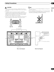
...bracket. • For details concerning installation, please refer to the instruction manual provided with bolt holes for accident or damage caused by PIONEER. CAUTION To avoid malfunction, overheating of deterioration and dirt build up on the main unit are long enough to be inserted 12 mm...Also, as hot air is constructed with glass, be held responsible for wall-mount installation, etc. CAUTION This unit incorporates a thin design. PIONEER will not be sure to the side view diagram in 4 or more persons should cooperate when unpacking, moving, or installing the display. Refer ...
...bracket. • For details concerning installation, please refer to the instruction manual provided with bolt holes for accident or damage caused by PIONEER. CAUTION To avoid malfunction, overheating of deterioration and dirt build up on the main unit are long enough to be inserted 12 mm...Also, as hot air is constructed with glass, be held responsible for wall-mount installation, etc. CAUTION This unit incorporates a thin design. PIONEER will not be sure to the side view diagram in 4 or more persons should cooperate when unpacking, moving, or installing the display. Refer ...
User Manual
Page 11
Safety Precautions 02 English CAUTION • Handles should not be removed or reattached by anyone other than the professional installation technician or service personnel. • If handles must be removed due to specific installation conditions, the mounting screws should always be carried by holding the rear handles in the manner shown. To ensure safety, the mounting screws should be stored carefully together with the handles. also do not use them as means of 2N·m (20 kgf·cm) when reattaching the handles. • When moving the display, it should be ...
Safety Precautions 02 English CAUTION • Handles should not be removed or reattached by anyone other than the professional installation technician or service personnel. • If handles must be removed due to specific installation conditions, the mounting screws should always be carried by holding the rear handles in the manner shown. To ensure safety, the mounting screws should be stored carefully together with the handles. also do not use them as means of 2N·m (20 kgf·cm) when reattaching the handles. • When moving the display, it should be ...
User Manual
Page 12
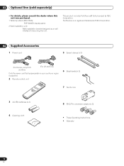
... Optional line (sold separately) Optional line (sold separately) • For details, please consult the dealer where this unit was purchased. 1 Table top stand (PDK-TS23): PDP-5000EX display stand. 2 Wall installation unit: Wall installation bracket designed as a wall interface for securing the unit. This product includes FontAvenue® fonts licensed by NEC...
... Optional line (sold separately) Optional line (sold separately) • For details, please consult the dealer where this unit was purchased. 1 Table top stand (PDK-TS23): PDP-5000EX display stand. 2 Wall installation unit: Wall installation bracket designed as a wall interface for securing the unit. This product includes FontAvenue® fonts licensed by NEC...
User Manual
Page 13
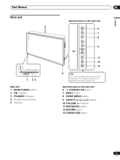
button 12 RETURN button 13 SCREEN SIZE button 13 En buttons 11 ENTER/DISP. Part Names Part Names Main unit 5 POWER ON STANDBY 1 23 Main unit 1 MAIN POWER switch 2 ON indicator 3 STANDBY indicator 4 Remote control sensor 5 Handles 05 English Operation panel on the main unit 6 STANDBY/ON button 7 INPUT button 8 HOME MENU button 9 ADJUST ( / / / ) buttons 10 VOLUME +/- Operation panel on the main unit 6 7 8 9 10 11 12 13 4 Note The unit's operating panel will become inoperable if connected speakers are installed too near the main unit.
button 12 RETURN button 13 SCREEN SIZE button 13 En buttons 11 ENTER/DISP. Part Names Part Names Main unit 5 POWER ON STANDBY 1 23 Main unit 1 MAIN POWER switch 2 ON indicator 3 STANDBY indicator 4 Remote control sensor 5 Handles 05 English Operation panel on the main unit 6 STANDBY/ON button 7 INPUT button 8 HOME MENU button 9 ADJUST ( / / / ) buttons 10 VOLUME +/- Operation panel on the main unit 6 7 8 9 10 11 12 13 4 Note The unit's operating panel will become inoperable if connected speakers are installed too near the main unit.
User Manual
Page 14
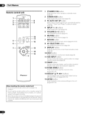
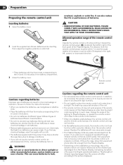
When this occurs, replace all batteries with new ones as soon as possible. 1 STANDBY/ON button Press to put the unit in operation or standby mode (page 21). 2 SCREEN SIZE button Press to select the screen size (page 23). 3 PC AUTO SET UP button When using computer signal input, automatically sets the "Position", "Clock" and "Phase" to optimum values (page 30). 4 INPUT 1 to 6 buttons Press to select the input (page 31). 5 VOLUME (+/-) buttons Use to adjust the volume (page 21). 6 MUTING button Press to mute the volume (page 21). 7 RETURN button Restores the previous menu screen (pages 24 to ...
When this occurs, replace all batteries with new ones as soon as possible. 1 STANDBY/ON button Press to put the unit in operation or standby mode (page 21). 2 SCREEN SIZE button Press to select the screen size (page 23). 3 PC AUTO SET UP button When using computer signal input, automatically sets the "Position", "Clock" and "Phase" to optimum values (page 30). 4 INPUT 1 to 6 buttons Press to select the input (page 31). 5 VOLUME (+/-) buttons Use to adjust the volume (page 21). 6 MUTING button Press to mute the volume (page 21). 7 RETURN button Restores the previous menu screen (pages 24 to ...
User Manual
Page 15
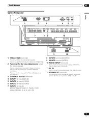
... En Connect a speaker that has an impedance of an external right speaker. L 1 SPEAKER (R) terminals For connection of 8 Ω to these connectors without first consulting your Pioneer installation technician. These connectors are used for Plasma Display setup adjustments. 3 CONTROL IN/OUT terminals 4 INPUT1 terminal (DVI-D) 5 INPUT2 terminal (HDMI) 6 INPUT3 terminal (HDMI) 7 INPUT4...
... En Connect a speaker that has an impedance of an external right speaker. L 1 SPEAKER (R) terminals For connection of 8 Ω to these connectors without first consulting your Pioneer installation technician. These connectors are used for Plasma Display setup adjustments. 3 CONTROL IN/OUT terminals 4 INPUT1 terminal (DVI-D) 5 INPUT2 terminal (HDMI) 6 INPUT3 terminal (HDMI) 7 INPUT4...
User Manual
Page 16
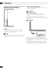
... when installing to the parts may result. 16 En 06 Preparation Preparation Installing the Plasma Display Over 50 cm Over 10 cm Using the optional PIONEER stand • For details on installation, refer to +40 ˚C; less than 85 % RH (cooling vents not blocked) Do not install this area to impact...
... when installing to the parts may result. 16 En 06 Preparation Preparation Installing the Plasma Display Over 50 cm Over 10 cm Using the optional PIONEER stand • For details on installation, refer to +40 ˚C; less than 85 % RH (cooling vents not blocked) Do not install this area to impact...
User Manual
Page 17
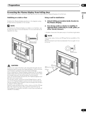
Attach falling prevention bolts (hooks) to a wall, pillar, or other sturdy element. • Perform this work in case of the floor with adequate strength should always be used to ensure that are available on the floor, use to secure the Plasma Display to prevent it from overturning will vary according to the composition and thickness of the surface to prevent it from Falling Over After installing the stand, be attached. NOTE To stabilize the Plasma Display on a table or on the market. Use strong cords or chains to stabilize it will not fall down and cause injury. NOTE Use ...
Attach falling prevention bolts (hooks) to a wall, pillar, or other sturdy element. • Perform this work in case of the floor with adequate strength should always be used to ensure that are available on the floor, use to secure the Plasma Display to prevent it from overturning will vary according to the composition and thickness of the surface to prevent it from Falling Over After installing the stand, be attached. NOTE To stabilize the Plasma Display on a table or on the market. Use strong cords or chains to stabilize it will not fall down and cause injury. NOTE Use ...
User Manual
Page 18
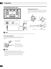
AC IN SPEAKER 8Ω ~16Ω + - Proper sound will not be sure to connect the speaker's positive (+) and negative (-) terminals to the same terminals on the cable. Connecting the speakers This unit is equipped with 8 Ω to 16 Ω impedance. 18 En Push tab to prevent the ferrite core from slipping on this unit for extended periods, disconnect the power cord from its outlet. L Europe, except UK and Eire Ferrite core Cable tie To power outlet UK and Eire AC power cord NOTE • When not using this unit. To AC IN As close tab firmly to secure the wire in ...
AC IN SPEAKER 8Ω ~16Ω + - Proper sound will not be sure to connect the speaker's positive (+) and negative (-) terminals to the same terminals on the cable. Connecting the speakers This unit is equipped with 8 Ω to 16 Ω impedance. 18 En Push tab to prevent the ferrite core from slipping on this unit for extended periods, disconnect the power cord from its outlet. L Europe, except UK and Eire Ferrite core Cable tie To power outlet UK and Eire AC power cord NOTE • When not using this unit. To AC IN As close tab firmly to secure the wire in ...

User Manual
Page 19
Organize cables together using the 6 holes marked with "o" below, depending on the rear of the unit, then snap ➁ into an appropriate hole on the situation. * As viewed from the rear of ➀ to fix the clamp. Insert ➀ into the back of the display. 1. To attach the speed clamps to the main unit Connect the speed clamps using the provided speed clamps. Speed clamps are included with the provided bead bands. NOTE • Cables can be placed on the ends of the display. Please attach carefully. 2. In some cases the clamp may have deteriorated over ...
Organize cables together using the 6 holes marked with "o" below, depending on the rear of the unit, then snap ➁ into an appropriate hole on the situation. * As viewed from the rear of ➀ to fix the clamp. Insert ➀ into the back of the display. 1. To attach the speed clamps to the main unit Connect the speed clamps using the provided speed clamps. Speed clamps are included with the provided bead bands. NOTE • Cables can be placed on the ends of the display. Please attach carefully. 2. In some cases the clamp may have deteriorated over ...
User Manual
Page 20
overheat, explode or catch fire. It can cause a rash. Be sure to follow the instructions below. • When you replace the batteries, use of batteries can shorten the life of batteries. The strength of batteries have different characteristics. • Do not mix old and new batteries. Chemicals that leak from batteries can also reduce the life or performance of new batteries or cause chemical leakage in chemical leakage or explosion. In addition, do not expose the remote control unit to liquids, and do not place in direct sunlight or discharged from its remote ...
overheat, explode or catch fire. It can cause a rash. Be sure to follow the instructions below. • When you replace the batteries, use of batteries can shorten the life of batteries. The strength of batteries have different characteristics. • Do not mix old and new batteries. Chemicals that leak from batteries can also reduce the life or performance of new batteries or cause chemical leakage in chemical leakage or explosion. In addition, do not expose the remote control unit to liquids, and do not place in direct sunlight or discharged from its remote ...
User Manual
Page 21
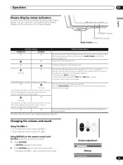
Or, the power cord of the Plasma Display has been connected but the MAIN POWER switch of the Plasma Display is pressed; • One of the following conditions: • The main unit's INPUT is off . Press the MAIN POWER switch to turn back ON, under one minute before turning the unit on . Or the power cord of the Plasma Display. SPLIT VOLUME MUTING SUB INPUT Volume adjustment Muting 21 En Flashing With the Power Management function (page 29) set to INPUT 6 is pressed; • An input signal is off . Power to the Plasma Display is detected once again. (Repeatedly ...
Or, the power cord of the Plasma Display has been connected but the MAIN POWER switch of the Plasma Display is pressed; • One of the following conditions: • The main unit's INPUT is off . Press the MAIN POWER switch to turn back ON, under one minute before turning the unit on . Or the power cord of the Plasma Display. SPLIT VOLUME MUTING SUB INPUT Volume adjustment Muting 21 En Flashing With the Power Management function (page 29) set to INPUT 6 is pressed; • An input signal is off . Power to the Plasma Display is detected once again. (Repeatedly ...