Owner's Manual
Page 3
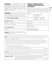
...connectors for connections. Product Name: Plasma Display System (Plasma Display) (Media Receiver) Model Number: PDP-5060HD PDP-4360HD (PDP-506PU) (PDP-436PU) (PDP-R06U) (PDP-R06U) Product Category: Class B Personal Computers & Peripherals Responsible Party Name: PIONEER ELECTRONICS SERVICE, INC. DOMINGUEZ ST. However, there is subject to...For Canadian model] This Class B digital apparatus complies with Canadian ICES-003. Increase the separation between the equipment and receiver. - WARNING: Handling the cord on this equipment into an outlet on , the user is encouraged to try to...
...connectors for connections. Product Name: Plasma Display System (Plasma Display) (Media Receiver) Model Number: PDP-5060HD PDP-4360HD (PDP-506PU) (PDP-436PU) (PDP-R06U) (PDP-R06U) Product Category: Class B Personal Computers & Peripherals Responsible Party Name: PIONEER ELECTRONICS SERVICE, INC. DOMINGUEZ ST. However, there is subject to...For Canadian model] This Class B digital apparatus complies with Canadian ICES-003. Increase the separation between the equipment and receiver. - WARNING: Handling the cord on this equipment into an outlet on , the user is encouraged to try to...
Owner's Manual
Page 4
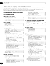
...Guidance Information 02 Safety Precautions 03 Supplied Accessories Identifying the main units 12 Plasma Display 12 Media Receiver 12 04 Part Names Plasma Display 13 Media Receiver 14 Remote control unit 16 Setting MTS/SAP mode 28 Viewing a channel banner 29 Using ... up the TV Guide On Screen™ system 31 05 Preparation Installing the Plasma Display 17 Installing the Media Receiver 17 Preventing the Plasma Display from Falling Over 18 08 Menu Setup Menu Configuration 37 AV mode menus 37... may sometimes differ from that shown in a safe place for buying this Pioneer product.
...Guidance Information 02 Safety Precautions 03 Supplied Accessories Identifying the main units 12 Plasma Display 12 Media Receiver 12 04 Part Names Plasma Display 13 Media Receiver 14 Remote control unit 16 Setting MTS/SAP mode 28 Viewing a channel banner 29 Using ... up the TV Guide On Screen™ system 31 05 Preparation Installing the Plasma Display 17 Installing the Media Receiver 17 Preventing the Plasma Display from Falling Over 18 08 Menu Setup Menu Configuration 37 AV mode menus 37... may sometimes differ from that shown in a safe place for buying this Pioneer product.
Owner's Manual
Page 7
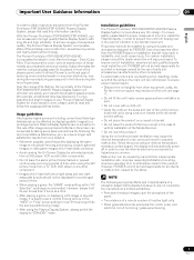
...Media Receiver. • Do not invert the product. Malfunction can ensure longer and satisfactory results from tipping over except in order to prevent the unit from your Pioneer Plasma Display System for a prolonged period. Direct Color Filter. Plasma Display Systems are no exception to this product. Installation guidelines The Pioneer PureVision PDP-5060HD/PDP-4360HD...above. To ensure proper heat emission: • Distance the unit slightly from this Pioneer PureVision PDP-5060HD/PDP-4360HD Plasma Display System, please first read and follow the usage guidelines below , you...
...Media Receiver. • Do not invert the product. Malfunction can ensure longer and satisfactory results from tipping over except in order to prevent the unit from your Pioneer Plasma Display System for a prolonged period. Direct Color Filter. Plasma Display Systems are no exception to this product. Installation guidelines The Pioneer PureVision PDP-5060HD/PDP-4360HD...above. To ensure proper heat emission: • Distance the unit slightly from this Pioneer PureVision PDP-5060HD/PDP-4360HD Plasma Display System, please first read and follow the usage guidelines below , you...
Owner's Manual
Page 8
... If you use the handles to a warm place or just after a heater is switched on on the surface or inside of the Media Receiver becomes high. characteristics. Depending on how the Plasma Display is in either a black or colored pixel permanently fixed on , resulting in &#...the cabinet hard, the surface color displays then this is considered normal for this product, gently wipe it emits a small amount of noise. All Pioneer display panels are visible at a normal viewing distance of between 2.5 and 3.5 meters (8.2 and 11.5 feet) while viewing a normal broadcast (i.e. ...
... If you use the handles to a warm place or just after a heater is switched on on the surface or inside of the Media Receiver becomes high. characteristics. Depending on how the Plasma Display is in either a black or colored pixel permanently fixed on , resulting in &#...the cabinet hard, the surface color displays then this is considered normal for this product, gently wipe it emits a small amount of noise. All Pioneer display panels are visible at a normal viewing distance of between 2.5 and 3.5 meters (8.2 and 11.5 feet) while viewing a normal broadcast (i.e. ...
Owner's Manual
Page 12
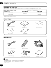
... following table to check that you have received the correct Media Receiver and Plasma Receiver models. Model Name of the Main Unit Media Receiver Plasma Display PDP-R06U PDP-506PU PDP-436PU Plasma Display Power cord (2 m/6.6 feet) Bead band × 3 Media Receiver Cleaning cloth Warranty card Speed clamp ×...; Always use the power cord supplied with the Plasma Display and the one supplied with the Media Receiver for each respective unit. 12 En Operating instructions Model Name of the Entire Plasma Display System PDP-5060HD PDP-4360HD The speakers are available as options.
... following table to check that you have received the correct Media Receiver and Plasma Receiver models. Model Name of the Main Unit Media Receiver Plasma Display PDP-R06U PDP-506PU PDP-436PU Plasma Display Power cord (2 m/6.6 feet) Bead band × 3 Media Receiver Cleaning cloth Warranty card Speed clamp ×...; Always use the power cord supplied with the Plasma Display and the one supplied with the Media Receiver for each respective unit. 12 En Operating instructions Model Name of the Entire Plasma Display System PDP-5060HD PDP-4360HD The speakers are available as options.

Owner's Manual
Page 14
... (AUDIO) 13 PC INPUT terminal (ANALOG RGB) The buttons with asterisks (*) can operate the TV Guide On Screen™ system. 14 En 04 Part Names Media Receiver Front view 123 STANDBY/ON REC ON STANDBY TIMER PULL OPEN Pull this section to open the door.
... (AUDIO) 13 PC INPUT terminal (ANALOG RGB) The buttons with asterisks (*) can operate the TV Guide On Screen™ system. 14 En 04 Part Names Media Receiver Front view 123 STANDBY/ON REC ON STANDBY TIMER PULL OPEN Pull this section to open the door.
Owner's Manual
Page 17
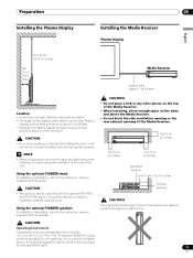
... used only with the optional PDK-TS10 and PDK-FS06 stand. Maintain adequate ventilation. • The length of the Media Receiver, it . Using the optional PIONEER speakers For details on installation, refer to have someone help you place anything on the sides and above the...This product can be used to connect the Plasma Display and the Media Receiver is about 3 m (9.8 feet). • Because the Plasma Display is heavy, be sure to the instruction manual supplied with the speaker. Using the optional PIONEER stand For details on installation, refer to high humidity or direct...
... used only with the optional PDK-TS10 and PDK-FS06 stand. Maintain adequate ventilation. • The length of the Media Receiver, it . Using the optional PIONEER speakers For details on installation, refer to have someone help you place anything on the sides and above the...This product can be used to connect the Plasma Display and the Media Receiver is about 3 m (9.8 feet). • Because the Plasma Display is heavy, be sure to the instruction manual supplied with the speaker. Using the optional PIONEER stand For details on installation, refer to high humidity or direct...
Owner's Manual
Page 19
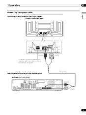
... Display (rear view) SYSTEM CABLE WHITE BLACK SYSTEM CABLE WHITE BLACK (BLACK) For details on optional PIONEER speaker installation, refer to the instruction manual that came with the speaker. (WHITE) Connecting the system cable to the Media Receiver Media Receiver (rear view) MONITOR OUT ANT/ CABLE A IN INPUT 2 G-LINK INPUT 3 S400 (TS) R-AUDIO-L OPTICAL DIGITAL...
... Display (rear view) SYSTEM CABLE WHITE BLACK SYSTEM CABLE WHITE BLACK (BLACK) For details on optional PIONEER speaker installation, refer to the instruction manual that came with the speaker. (WHITE) Connecting the system cable to the Media Receiver Media Receiver (rear view) MONITOR OUT ANT/ CABLE A IN INPUT 2 G-LINK INPUT 3 S400 (TS) R-AUDIO-L OPTICAL DIGITAL...
Owner's Manual
Page 20
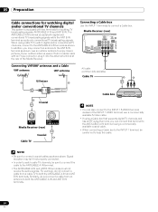
...Connecting VHF/UHF antennas and a Cable VHF antenna UHF antenna U/Vmixer AV cable (commercially available) Cable TV Coaxial ANT B IN ANT/ CABLE A IN Media Receiver (rear) Cable TV Coaxial Cable box NOTE • You can connect that terminal to the ANT/CABLE A IN terminal using a commercially available coaxial ...ANT/CABLE A IN and ANT B IN terminals. 20 En Signal reception may connect an antenna to the INPUT 1 S-VIDEO terminal instead of the Media Receiver. Similarly, do not connect a cable from an antenna to the ANT/CABLE A IN terminal. • The ANT/CABLE A IN and ANT ...
...Connecting VHF/UHF antennas and a Cable VHF antenna UHF antenna U/Vmixer AV cable (commercially available) Cable TV Coaxial ANT B IN ANT/ CABLE A IN Media Receiver (rear) Cable TV Coaxial Cable box NOTE • You can connect that terminal to the ANT/CABLE A IN terminal using a commercially available coaxial ...ANT/CABLE A IN and ANT B IN terminals. 20 En Signal reception may connect an antenna to the INPUT 1 S-VIDEO terminal instead of the Media Receiver. Similarly, do not connect a cable from an antenna to the ANT/CABLE A IN terminal. • The ANT/CABLE A IN and ANT ...

Owner's Manual
Page 21
... cable channel list. 21 En S400 (TS) R-AUDIO-L DIOGPITTAICLASOLUUBT WOOFER Cable CARD BLACK WHITE STEM CABLE NOTE • Be sure to view the image received from the Cable Converter. the POD stands for inserting a CableCARD™. This service presents various types of useful information, using HTML text. 1 Confirm that ...display the TV image of the other antenna. • Pressing ANT while watching in the 2-screen mode with a slot for Point of the Media Receiver, and remove the cover while releasing the tab's latch. Preparation 05 English Inserting the CableCARD™ The...
... cable channel list. 21 En S400 (TS) R-AUDIO-L DIOGPITTAICLASOLUUBT WOOFER Cable CARD BLACK WHITE STEM CABLE NOTE • Be sure to view the image received from the Cable Converter. the POD stands for inserting a CableCARD™. This service presents various types of useful information, using HTML text. 1 Confirm that ...display the TV image of the other antenna. • Pressing ANT while watching in the 2-screen mode with a slot for Point of the Media Receiver, and remove the cover while releasing the tab's latch. Preparation 05 English Inserting the CableCARD™ The...
Owner's Manual
Page 23
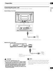
... three-core power cord with a ground terminal is used for efficient • Always turn off the power of the Plasma Display and Media Receiver when connecting or disconnecting power cords. • Disconnect the power cord from the power outlet when the Plasma Display System is properly grounded.... Always connect the power cord to a three-pronged outlet and make sure that the cord is not going to use the specified power supply voltage; Media Receiver (rear view) MONITOR OUT ANT/ CABLE A IN INPUT 2 G-LINK INPUT 3 S400 (TS) R-AUDIO-L OPTICAL DIGITAL OUT SUB WOOFER Cable CARD I ...
... three-core power cord with a ground terminal is used for efficient • Always turn off the power of the Plasma Display and Media Receiver when connecting or disconnecting power cords. • Disconnect the power cord from the power outlet when the Plasma Display System is properly grounded.... Always connect the power cord to a three-pronged outlet and make sure that the cord is not going to use the specified power supply voltage; Media Receiver (rear view) MONITOR OUT ANT/ CABLE A IN INPUT 2 G-LINK INPUT 3 S400 (TS) R-AUDIO-L OPTICAL DIGITAL OUT SUB WOOFER Cable CARD I ...
Owner's Manual
Page 25
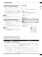
...on the remote control unit or STANDBY/ ON on the Media Receiver to the system is on the Plasma Display and Media Receiver. Or the power cord of the Media Receiver has been disconnected. Indicator Status Plasma Display Media Receiver POWER ON STANDBY POWER ON STANDBY System Status The power ...for a long period of the Plasma Display is in the standby mode. Plasma Display STANDBY indicator POWER ON indicator POWER button Media Receiver Turning off . STANDBY/ON REC ON STANDBY TIMER STANDBY indicator POWER ON indicator STANDBY/ON button NOTE • If you ...
...on the remote control unit or STANDBY/ ON on the Media Receiver to the system is on the Plasma Display and Media Receiver. Or the power cord of the Media Receiver has been disconnected. Indicator Status Plasma Display Media Receiver POWER ON STANDBY POWER ON STANDBY System Status The power ...for a long period of the Plasma Display is in the standby mode. Plasma Display STANDBY indicator POWER ON indicator POWER button Media Receiver Turning off . STANDBY/ON REC ON STANDBY TIMER STANDBY indicator POWER ON indicator STANDBY/ON button NOTE • If you ...
Owner's Manual
Page 26
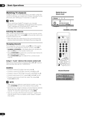
...remote control unit Select channels directly by TV stations as CH +/- Changing channels To increase the channel number, press CH + on the Media Receiver operates the same as necessary when in those channels. EXAMPLE • To select channel 5 (1-digit channel), press 5. • To ... 10.01, press 1, 0, • (dot), 0, then 1. • To select subchannel 10.001 (for cable TV), press 1, 0, • (dot), 0, 0, then 1. Media Receiver (front view) STANDBY/ON REC ON STANDBY TIMER TV GUIDE ENTER DOWN UP LEFT RIGHT INPUT DOWN UP VOLUME DOWN UP CHANNEL CHANNEL UP/DOWN...
...remote control unit Select channels directly by TV stations as CH +/- Changing channels To increase the channel number, press CH + on the Media Receiver operates the same as necessary when in those channels. EXAMPLE • To select channel 5 (1-digit channel), press 5. • To ... 10.01, press 1, 0, • (dot), 0, then 1. • To select subchannel 10.001 (for cable TV), press 1, 0, • (dot), 0, 0, then 1. Media Receiver (front view) STANDBY/ON REC ON STANDBY TIMER TV GUIDE ENTER DOWN UP LEFT RIGHT INPUT DOWN UP VOLUME DOWN UP CHANNEL CHANNEL UP/DOWN...
Owner's Manual
Page 27
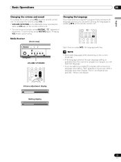
...With a language other than English, French, and Spanish are watching a digital TV program without sound or language information, "N/A" appears on the Media Receiver operates the same as VOL +/- NOTE • Switchable languages differ depending on the current broadcast. • If the language selected through ... To decrease the volume, press VOL -. • VOLUME UP/DOWN on the screen. Volume adjustment display Muting display 27 En Media Receiver (front view) STANDBY/ON REC ON STANDBY TIMER TV GUIDE ENTER DOWN UP LEFT RIGHT INPUT DOWN UP VOLUME DOWN UP CHANNEL...
...With a language other than English, French, and Spanish are watching a digital TV program without sound or language information, "N/A" appears on the Media Receiver operates the same as VOL +/- NOTE • Switchable languages differ depending on the current broadcast. • If the language selected through ... To decrease the volume, press VOL -. • VOLUME UP/DOWN on the screen. Volume adjustment display Muting display 27 En Media Receiver (front view) STANDBY/ON REC ON STANDBY TIMER TV GUIDE ENTER DOWN UP LEFT RIGHT INPUT DOWN UP VOLUME DOWN UP CHANNEL...
Owner's Manual
Page 38
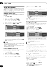
...Auto Channel Preset". • Executing more than one scan for cables will locate the CableCARD™ slot on the rear of the Media Receiver. A Signal Strength Signal Strength Maximum: 100 Current: 100 xxxxxxxxxxxxxxxxxxxxx xxxxxxxxxxxxxxxxxxxxx xxxxxxxxxxxxxxxxxxxxx Home Menu Exit • Adjust the direction of a...appears. 7 Press A to complete the setup process. 8 Press HOME MENU to exit the menu. Checking the CableCARD™ ID The Media Receiver has a slot for a CableCARD™ that you may need to manually add Cable Converter output channels. • When an inserted ...
...Auto Channel Preset". • Executing more than one scan for cables will locate the CableCARD™ slot on the rear of the Media Receiver. A Signal Strength Signal Strength Maximum: 100 Current: 100 xxxxxxxxxxxxxxxxxxxxx xxxxxxxxxxxxxxxxxxxxx xxxxxxxxxxxxxxxxxxxxx Home Menu Exit • Adjust the direction of a...appears. 7 Press A to complete the setup process. 8 Press HOME MENU to exit the menu. Checking the CableCARD™ ID The Media Receiver has a slot for a CableCARD™ that you may need to manually add Cable Converter output channels. • When an inserted ...
Owner's Manual
Page 46
... 46 En Records the same program any day it may take up to one of listings may take up to 24 hours to begin to receive TV program listings. The program is set to record, but is suspended because of Gemstar-TV Guide International, Inc. Half-hour time slots are... Screen™ system Before you can start using the TV Guide On Screen™ system, you'll need to correctly connect the equipment to the Media Receiver. The program is available; One-time only recording • Record Daily - The recording resumes when the conflict is broadcast in the SCHEDULE list,...
... 46 En Records the same program any day it may take up to one of listings may take up to 24 hours to begin to receive TV program listings. The program is set to record, but is suspended because of Gemstar-TV Guide International, Inc. Half-hour time slots are... Screen™ system Before you can start using the TV Guide On Screen™ system, you'll need to correctly connect the equipment to the Media Receiver. The program is available; One-time only recording • Record Daily - The recording resumes when the conflict is broadcast in the SCHEDULE list,...
Owner's Manual
Page 47
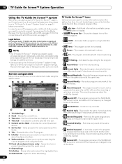
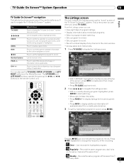
... you can also use to exit). /// Use to display listings for later time slots. • Press PAGE+/- Key TV GUIDE What it airs on the Media Receiver. Records the same program any channel in the video window. • Access panel and channel ads. 1 Press TV GUIDE to navigate the TV Guide On...
... you can also use to exit). /// Use to display listings for later time slots. • Press PAGE+/- Key TV GUIDE What it airs on the Media Receiver. Records the same program any channel in the video window. • Access panel and channel ads. 1 Press TV GUIDE to navigate the TV Guide On...

Owner's Manual
Page 62
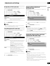
... the system into the standby mode. (factory default) Enable Places the system into the standby mode when noise signals are present at the Media Receiver after a TV program finishes. 62 En 11 Adjustments and Settings FOCUS This shifts the sound-source direction (sound image) upward and produces ... FOCUS. 5 Press HOME MENU to save power. Energy Save You may not be automatically placed into the standby mode if no signal is received for Front Surround. • is a trademark of the three Energy Save modes to exit the menu. Save2 Decreases the picture brightness and lowers...
... the system into the standby mode. (factory default) Enable Places the system into the standby mode when noise signals are present at the Media Receiver after a TV program finishes. 62 En 11 Adjustments and Settings FOCUS This shifts the sound-source direction (sound image) upward and produces ... FOCUS. 5 Press HOME MENU to save power. Energy Save You may not be automatically placed into the standby mode if no signal is received for Front Surround. • is a trademark of the three Energy Save modes to exit the menu. Save2 Decreases the picture brightness and lowers...
Owner's Manual
Page 63
..., the system is switched on. • The system is switched on again by pressing STANDBY/ON on the Media Receiver or TV on conditions. • Auto Setup may have failed, depending on the remote control unit. appears, Auto Setup may fail with a.... 1 Press HOME MENU. 2 Select "Power Control". ( / then ENTER) 3 Select "No Operation off . • The system is switched on again by pressing STANDBY/ON on the Media Receiver or TV on the Plasma Display. 1 Press HOME MENU. 2 Select "Option". ( / then ENTER) 3 Select "Position". ( / then ENTER) 4 Select "H/V Position Adjust". ( / then ENTER) ...
..., the system is switched on. • The system is switched on again by pressing STANDBY/ON on the Media Receiver or TV on conditions. • Auto Setup may have failed, depending on the remote control unit. appears, Auto Setup may fail with a.... 1 Press HOME MENU. 2 Select "Power Control". ( / then ENTER) 3 Select "No Operation off . • The system is switched on again by pressing STANDBY/ON on the Media Receiver or TV on the Plasma Display. 1 Press HOME MENU. 2 Select "Option". ( / then ENTER) 3 Select "Position". ( / then ENTER) 4 Select "H/V Position Adjust". ( / then ENTER) ...
Owner's Manual
Page 67
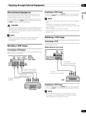
... they are to select INPUT1. Watching a DVD image Connecting a DVD player Use the INPUT 1 terminals when connecting a DVD player and other audiovisual equipment. Media Receiver (rear view) MONITOR OUT ANT/ CABLE A IN INPUT 2 G-LINK INPUT 3 I N OUT CONTROL ANT B IN SERVICE ONLY R-AUDIO-L VIDEO S-VIDEO...VCR DVD player Displaying a VCR image To watch a DVD image, press INPUT 1 on the remote control unit or press INPUT on the Media Receiver. NOTE • The INPUT 2 terminals are checked whether they are connected in the following order; 1) Component Video, 2) SVideo, 3) Video...
... they are to select INPUT1. Watching a DVD image Connecting a DVD player Use the INPUT 1 terminals when connecting a DVD player and other audiovisual equipment. Media Receiver (rear view) MONITOR OUT ANT/ CABLE A IN INPUT 2 G-LINK INPUT 3 I N OUT CONTROL ANT B IN SERVICE ONLY R-AUDIO-L VIDEO S-VIDEO...VCR DVD player Displaying a VCR image To watch a DVD image, press INPUT 1 on the remote control unit or press INPUT on the Media Receiver. NOTE • The INPUT 2 terminals are checked whether they are connected in the following order; 1) Component Video, 2) SVideo, 3) Video...


