
Owner's Manual
Page 2
...moisture, does not operate normally, or has been dropped. A security card provided by direct connection to a cable system providing such programming. Install in any way, such as video-ondemand, a cable operator's enhanced program guide and data-enhanced television services may require the use of receiving analog basic, digital basic... is damaged, liquid has been spilled or objects have fallen into your outlet, consult an electrician for your local cable operator. A grounding type plug has two blades and a third grounding prong. The wide blade or the third prong are provided for ...
...moisture, does not operate normally, or has been dropped. A security card provided by direct connection to a cable system providing such programming. Install in any way, such as video-ondemand, a cable operator's enhanced program guide and data-enhanced television services may require the use of receiving analog basic, digital basic... is damaged, liquid has been spilled or objects have fallen into your outlet, consult an electrician for your local cable operator. A grounding type plug has two blades and a third grounding prong. The wide blade or the third prong are provided for ...
Owner's Manual
Page 3
... (Media Receiver) Model Number: PDP-5060HD PDP-4360HD (PDP-506PU) (PDP-436PU) (PDP-R06U) (PDP-R06U) Product Category: Class B Personal Computers & Peripherals Responsible Party Name: PIONEER ELECTRONICS SERVICE, INC. D8-10-1-2_En CAUTION: This product satisfies FCC regulations when shielded cables and connectors are designed to radio... cord on a circuit different from that to comply with electric appliances such as radios and televisions, use shielded cables and connectors for connections. NOTE: This equipment has been tested and found to which can radiate radio frequency energy...
... (Media Receiver) Model Number: PDP-5060HD PDP-4360HD (PDP-506PU) (PDP-436PU) (PDP-R06U) (PDP-R06U) Product Category: Class B Personal Computers & Peripherals Responsible Party Name: PIONEER ELECTRONICS SERVICE, INC. D8-10-1-2_En CAUTION: This product satisfies FCC regulations when shielded cables and connectors are designed to radio... cord on a circuit different from that to comply with electric appliances such as radios and televisions, use shielded cables and connectors for connections. NOTE: This equipment has been tested and found to which can radiate radio frequency energy...
Owner's Manual
Page 4
...37 AV mode menus 37 PC mode menus 37 Menu operations 37 Connecting the system cable 19 Cable connections for watching digital and/or conventional TV channels 20 Connecting VHF/UHF antennas and a Cable 20 Connecting a Cable box 20 Inserting the CableCARD 21 Switching between antenna A and B .......21 Preparing ... Display 17 Installing the Media Receiver 17 Preventing the Plasma Display from that shown in a safe place for buying this Pioneer product. However the method of the remote control unit 22 Cautions regarding the remote control unit 22 Connecting the power cord 23 Routing...
...37 AV mode menus 37 PC mode menus 37 Menu operations 37 Connecting the system cable 19 Cable connections for watching digital and/or conventional TV channels 20 Connecting VHF/UHF antennas and a Cable 20 Connecting a Cable box 20 Inserting the CableCARD 21 Switching between antenna A and B .......21 Preparing ... Display 17 Installing the Media Receiver 17 Preventing the Plasma Display from that shown in a safe place for buying this Pioneer product. However the method of the remote control unit 22 Cautions regarding the remote control unit 22 Connecting the power cord 23 Routing...
Owner's Manual
Page 6
... the learning function 78 Presetting manufacturer codes ...........78 Manufacture codes 79 Using the remote control unit to control other devices 80 Receiver control buttons 80 Cable control buttons 81 SAT control buttons 82 VCR control buttons 83 DVD/DVR control buttons 84 14 Appendix Troubleshooting 85 Specifications 94 6 En
... the learning function 78 Presetting manufacturer codes ...........78 Manufacture codes 79 Using the remote control unit to control other devices 80 Receiver control buttons 80 Cable control buttons 81 SAT control buttons 82 VCR control buttons 83 DVD/DVR control buttons 84 14 Appendix Troubleshooting 85 Specifications 94 6 En

Owner's Manual
Page 11
...surface Mounting hole Mounting hole Median line Plasma Display Mounting bracket (or equivalent item) M8 screw 12 to 18 mm (0.5 to 0.7 inches) SYSTEM CABLE WHITE BLACK Median line CAUTION • Be sure to use of mounting items other than the above . • Be careful not to block ...specified products. • Do not mount or remove the Plasma Display to be liable for the specified products. When using other than the optional PIONEER products. 11 En NOTE • It is strongly recommended to use the supplied bolts. • For details, see the instruction manual that ...
...surface Mounting hole Mounting hole Median line Plasma Display Mounting bracket (or equivalent item) M8 screw 12 to 18 mm (0.5 to 0.7 inches) SYSTEM CABLE WHITE BLACK Median line CAUTION • Be sure to use of mounting items other than the above . • Be careful not to block ...specified products. • Do not mount or remove the Plasma Display to be liable for the specified products. When using other than the optional PIONEER products. 11 En NOTE • It is strongly recommended to use the supplied bolts. • For details, see the instruction manual that ...
Owner's Manual
Page 12
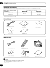
... of the Main Unit Media Receiver Plasma Display PDP-R06U PDP-506PU PDP-436PU Plasma Display Power cord (2 m/6.6 feet) Bead band × 3 Media Receiver Cleaning cloth Warranty card Speed clamp × 3 Power cord (2 m/6.6 feet) Remote control unit System cable (3 m/9.8 feet) AA size battery × 2 (Alkaline battery) G-LINK cable (3 m/9.8 feet) NOTE • Always use... table to check that you have received the correct Media Receiver and Plasma Receiver models. Model Name of the Entire Plasma Display System PDP-5060HD PDP-4360HD The speakers are available as options.
... of the Main Unit Media Receiver Plasma Display PDP-R06U PDP-506PU PDP-436PU Plasma Display Power cord (2 m/6.6 feet) Bead band × 3 Media Receiver Cleaning cloth Warranty card Speed clamp × 3 Power cord (2 m/6.6 feet) Remote control unit System cable (3 m/9.8 feet) AA size battery × 2 (Alkaline battery) G-LINK cable (3 m/9.8 feet) NOTE • Always use... table to check that you have received the correct Media Receiver and Plasma Receiver models. Model Name of the Entire Plasma Display System PDP-5060HD PDP-4360HD The speakers are available as options.
Owner's Manual
Page 13
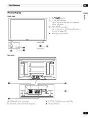
Part Names Part Names Plasma Display Front view 2 1 3 Rear view 04 1 a POWER button 2 STANDBY indicator Lights red when the unit is in standby mode. (page 25) 3 POWER ON indicator Lights blue when the Plasma Display is operating. (page 25) 4 Remote control sensor 4 English 5 SYSTEM CABLE WHITE BLACK SYSTEM CABLE WHITE BLACK 6 5 SPEAKER (R/L) terminals 6 SYSTEM CABLE terminal (BLACK) 7 8 7 SYSTEM CABLE terminal (WHITE) 8 AC IN terminal 13 En
Part Names Part Names Plasma Display Front view 2 1 3 Rear view 04 1 a POWER button 2 STANDBY indicator Lights red when the unit is in standby mode. (page 25) 3 POWER ON indicator Lights blue when the Plasma Display is operating. (page 25) 4 Remote control sensor 4 English 5 SYSTEM CABLE WHITE BLACK SYSTEM CABLE WHITE BLACK 6 5 SPEAKER (R/L) terminals 6 SYSTEM CABLE terminal (BLACK) 7 8 7 SYSTEM CABLE terminal (WHITE) 8 AC IN terminal 13 En
Owner's Manual
Page 15
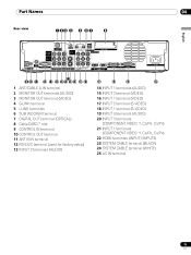
... SERVICE ONLY R-AUDIO-L VIDEO S-VIDEO INPUT 1 Y CB / PB COMPONENT VIDEO CR / PR INPUT 1 INPUT 3 HDMI BLACK WHITE SYSTEM CABLE AC IN 17 9 10 11 12 13 14 1516 18 19 20 21 1 ANT/CABLE A IN terminal 2 MONITOR OUT terminals (AUDIO) 3 MONITOR OUT terminal (VIDEO) 4 G-LINK terminal 5 i.LINK terminals 6 SUB WOOFER terminal 7 DIGITAL...
... SERVICE ONLY R-AUDIO-L VIDEO S-VIDEO INPUT 1 Y CB / PB COMPONENT VIDEO CR / PR INPUT 1 INPUT 3 HDMI BLACK WHITE SYSTEM CABLE AC IN 17 9 10 11 12 13 14 1516 18 19 20 21 1 ANT/CABLE A IN terminal 2 MONITOR OUT terminals (AUDIO) 3 MONITOR OUT terminal (VIDEO) 4 G-LINK terminal 5 i.LINK terminals 6 SUB WOOFER terminal 7 DIGITAL...
Owner's Manual
Page 17
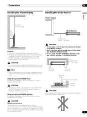
... Over 50 cm (19 11/16 inches) Over 10 cm (3 15/16 inches) Media Receiver STANDBY/ON REC ON STANDBY TIMER PULL OPEN System cable (approx. 3 m/9.8 feet) Location • Avoid direct sunlight. CAUTION • This product can result in product damage and malfunction. STANDBY/ON ... 5 cm (2 inches) Over 5 cm (2 inches) Ventilation opening Over 10 cm (3 15/16 inches) Exhaust opening of the unit. Using the optional PIONEER speakers For details on the sides and above the Media Receiver. • Do not block the side ventilation opening or the rear exhaust opening CAUTION...
... Over 50 cm (19 11/16 inches) Over 10 cm (3 15/16 inches) Media Receiver STANDBY/ON REC ON STANDBY TIMER PULL OPEN System cable (approx. 3 m/9.8 feet) Location • Avoid direct sunlight. CAUTION • This product can result in product damage and malfunction. STANDBY/ON ... 5 cm (2 inches) Over 5 cm (2 inches) Ventilation opening Over 10 cm (3 15/16 inches) Exhaust opening of the unit. Using the optional PIONEER speakers For details on the sides and above the Media Receiver. • Do not block the side ventilation opening or the rear exhaust opening CAUTION...
Owner's Manual
Page 19
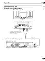
Preparation 05 English Connecting the system cable Connecting the system cable to the Plasma Display Plasma Display (rear view) SYSTEM CABLE WHITE BLACK SYSTEM CABLE WHITE BLACK (BLACK) For details on optional PIONEER speaker installation, refer to the instruction manual that came with the speaker. (WHITE) Connecting the system cable to the Media Receiver Media Receiver (rear...
Preparation 05 English Connecting the system cable Connecting the system cable to the Plasma Display Plasma Display (rear view) SYSTEM CABLE WHITE BLACK SYSTEM CABLE WHITE BLACK (BLACK) For details on optional PIONEER speaker installation, refer to the instruction manual that came with the speaker. (WHITE) Connecting the system cable to the Media Receiver Media Receiver (rear...
Owner's Manual
Page 20
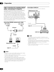
...R-AUDIO-L VIDEO S-VIDEO INPUT 1 COM V Connecting VHF/UHF antennas and a Cable VHF antenna UHF antenna U/Vmixer AV cable (commercially available) Cable TV Coaxial ANT B IN ANT/ CABLE A IN Media Receiver (rear) Cable TV Coaxial Cable box NOTE • You can connect that supports digital TV channels and has an...signals while the ANT B IN terminal accepts only conventional TV broadcasting signals. If your outdoor antenna uses a 75-ohm coaxial cable with two terminals for watching digital and/or conventional TV channels This system is equipped with an F-type connector, plug it into...
...R-AUDIO-L VIDEO S-VIDEO INPUT 1 COM V Connecting VHF/UHF antennas and a Cable VHF antenna UHF antenna U/Vmixer AV cable (commercially available) Cable TV Coaxial ANT B IN ANT/ CABLE A IN Media Receiver (rear) Cable TV Coaxial Cable box NOTE • You can connect that supports digital TV channels and has an...signals while the ANT B IN terminal accepts only conventional TV broadcasting signals. If your outdoor antenna uses a 75-ohm coaxial cable with two terminals for watching digital and/or conventional TV channels This system is equipped with an F-type connector, plug it into...

Owner's Manual
Page 21
...Point of Deployment. This service presents various types of the other antenna. • Pressing ANT while watching in the 2-screen mode with the coaxial cable from the other antenna. • Pressing ANT while watching in the 2-screen mode (TV image and video image) with TV selected will display... the TV image of useful information, using HTML text. 1 Confirm that the ANT/CABLE A IN terminal has been connected with two TV images displayed will not have any effect. the POD stands for inserting a CableCARD™. Tab Switching...
...Point of Deployment. This service presents various types of the other antenna. • Pressing ANT while watching in the 2-screen mode with the coaxial cable from the other antenna. • Pressing ANT while watching in the 2-screen mode (TV image and video image) with TV selected will display... the TV image of useful information, using HTML text. 1 Confirm that the ANT/CABLE A IN terminal has been connected with two TV images displayed will not have any effect. the POD stands for inserting a CableCARD™. Tab Switching...
Owner's Manual
Page 23
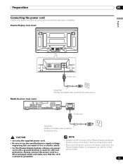
... ground terminal is used for efficient • Always turn off the power of time. Plasma Display (rear view) English SYSTEM CABLE WHITE BLACK SYSTEM CABLE WHITE BLACK Power cord Noise filter Partially eliminates noise caused by the power source. CAUTION NOTE • Use only the supplied...the cord is not going to use the specified power supply voltage; Media Receiver (rear view) MONITOR OUT ANT/ CABLE A IN INPUT 2 G-LINK INPUT 3 S400 (TS) R-AUDIO-L OPTICAL DIGITAL OUT SUB WOOFER Cable CARD I N OUT CONTROL ANT B IN SERVICE ONLY R-AUDIO-L VIDEO S-VIDEO INPUT 1 Y CB / PB...
... ground terminal is used for efficient • Always turn off the power of time. Plasma Display (rear view) English SYSTEM CABLE WHITE BLACK SYSTEM CABLE WHITE BLACK Power cord Noise filter Partially eliminates noise caused by the power source. CAUTION NOTE • Use only the supplied...the cord is not going to use the specified power supply voltage; Media Receiver (rear view) MONITOR OUT ANT/ CABLE A IN INPUT 2 G-LINK INPUT 3 S400 (TS) R-AUDIO-L OPTICAL DIGITAL OUT SUB WOOFER Cable CARD I N OUT CONTROL ANT B IN SERVICE ONLY R-AUDIO-L VIDEO S-VIDEO INPUT 1 Y CB / PB...
Owner's Manual
Page 24
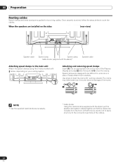
...deteriorate over time and become damaged if removed. 2 1 NOTE • Use the supplied bead bands as necessary. * Cable binder Using the cable binders supplied with the stand)* Speaker cable Attaching speed clamps to lock the clamp. Speed clamps are installed on the rear of the Plasma Display and snap [2] ...into the back of the cables. 24 En At that the cables are supplied for bunching cables. Use pliers to the connection sections of [1] to the main unit Attach the speed clamps using the 2 holes...
...deteriorate over time and become damaged if removed. 2 1 NOTE • Use the supplied bead bands as necessary. * Cable binder Using the cable binders supplied with the stand)* Speaker cable Attaching speed clamps to lock the clamp. Speed clamps are installed on the rear of the Plasma Display and snap [2] ...into the back of the cables. 24 En At that the cables are supplied for bunching cables. Use pliers to the connection sections of [1] to the main unit Attach the speed clamps using the 2 holes...
Owner's Manual
Page 26
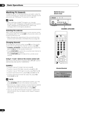
...; To select channel 125 (3-digit channel), press 1, 2, then 5. • To select subchannel 10.01, press 1, 0, • (dot), 0, then 1. • To select subchannel 10.001 (for cable TV), press 1, 0, • (dot), 0, 0, then 1. For the procedure, see emergency alert messages scrolling at the top of program information. Those messages are broadcasted by pressing...
...; To select channel 125 (3-digit channel), press 1, 2, then 5. • To select subchannel 10.01, press 1, 0, • (dot), 0, then 1. • To select subchannel 10.001 (for cable TV), press 1, 0, • (dot), 0, 0, then 1. For the procedure, see emergency alert messages scrolling at the top of program information. Those messages are broadcasted by pressing...
Owner's Manual
Page 28
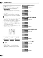
... you press MTS, MTS toggles as shown below. In this manual designate TV channels that are received through the conventional VHF/ UHF frequencies or conventional cable TV channels. • When stereo sound is difficult to hear, you may manually switch to the MONO mode to obtain clearer sound. • Once the...
... you press MTS, MTS toggles as shown below. In this manual designate TV channels that are received through the conventional VHF/ UHF frequencies or conventional cable TV channels. • When stereo sound is difficult to hear, you may manually switch to the MONO mode to obtain clearer sound. • Once the...

Owner's Manual
Page 29
...among 2-screen, picture-in-picture, and single-screen. Using the POD service If you have watched digital and/or High Definition TV channels over cable, you do not setup the TV Guide On Screen™ system, the channel banner may not display certain types of useful information, using ...press SPLIT, the display mode is not displayed if not included in broadcast signals. • If you can use the POD service provided by the cable TV company. Basic Operations 06 English Viewing a channel banner While watching a TV program, pressing INFO causes the following procedure to select the 2-screen...
...among 2-screen, picture-in-picture, and single-screen. Using the POD service If you have watched digital and/or High Definition TV channels over cable, you do not setup the TV Guide On Screen™ system, the channel banner may not display certain types of useful information, using ...press SPLIT, the display mode is not displayed if not included in broadcast signals. • If you can use the POD service provided by the cable TV company. Basic Operations 06 English Viewing a channel banner While watching a TV program, pressing INFO causes the following procedure to select the 2-screen...
Owner's Manual
Page 31
... shown on the current settings and selected items, the order of Transcontinental, Inc. NOTE • Once you set it may take up leads you connect a cable box through the setup process. The TV Guide On Screen™ system is a registered mark of the setup screens may be accessed from the one... GUIDE to begin to find out what's on right now or during the coming week, by channel or by pressing TV GUIDE for cable-ready, cable box, and digital cable services as well as over-the-air broadcast. Setting up to one week (see Screen 23). Receipt of all eight days of listings...
... shown on the current settings and selected items, the order of Transcontinental, Inc. NOTE • Once you set it may take up leads you connect a cable box through the setup process. The TV Guide On Screen™ system is a registered mark of the setup screens may be accessed from the one... GUIDE to begin to find out what's on right now or during the coming week, by channel or by pressing TV GUIDE for cable-ready, cable box, and digital cable services as well as over-the-air broadcast. Setting up to one week (see Screen 23). Receipt of all eight days of listings...

Owner's Manual
Page 33
...Screen 12. Screen 5: Which TV Guide input is properly installed. • Press ENTER to display Screen 7. Screen 8: Cable Box Brand Name • Press / to select a cable box brand. • Press ENTER to the cable box. Screen 7: Cable Box Configuration Diagram • The diagram shows the correct way to install the G-LINK... cable from the back of the device to display Screen 9. 33 En Make sure the G-LINK cable is the cable box plugged into? • If you select Cable, you see Screen 6. • If you make any other choice,...
...Screen 12. Screen 5: Which TV Guide input is properly installed. • Press ENTER to display Screen 7. Screen 8: Cable Box Brand Name • Press / to select a cable box brand. • Press ENTER to the cable box. Screen 7: Cable Box Configuration Diagram • The diagram shows the correct way to install the G-LINK... cable from the back of the device to display Screen 9. 33 En Make sure the G-LINK cable is the cable box plugged into? • If you select Cable, you see Screen 6. • If you make any other choice,...

Owner's Manual
Page 34
.... If you may see Screen 13. If you select "Yes", depending on -screen instructions, and press ENTER to display Screen 15. Screen 10: Cable Box Code Testing • When testing is done, Screen 11 displays automatically. After that screen, you see an additional screen. NOTE If you selected ...receive a channel lineup and listings. • If you select "No", you see Screen 13. 07 TV Guide On Screen™ System Setup Screen 9: Cable Box Preparation • Follow the on your setup configuration, you select "Test this screen to Channel 28? • If you select "Yes", you see...
.... If you may see Screen 13. If you select "Yes", depending on -screen instructions, and press ENTER to display Screen 15. Screen 10: Cable Box Code Testing • When testing is done, Screen 11 displays automatically. After that screen, you see an additional screen. NOTE If you selected ...receive a channel lineup and listings. • If you select "No", you see Screen 13. 07 TV Guide On Screen™ System Setup Screen 9: Cable Box Preparation • Follow the on your setup configuration, you select "Test this screen to Channel 28? • If you select "Yes", you see...


