Owner's Manual
Page 3
...keep it in accordance with part 15 of California and other reproductive harm. Reorient or relocate the receiving antenna. - CAUTION: This product satisfies FCC regulations when shielded cables and connectors are designed to...Name: Plasma Display System (Plasma Display) (Media Receiver) Model Number: PDP-5050HD PDP-4350HD (PDP-505PU) (PDP-435PU) (PDP-AR05U) (PDP-AR05U) PDP-5045HD PDP-4345HD (PDP-504PU) (PDP-434PU) (PDP-R05U) (PDP-R05U) Product Category: Class B Personal Computers & Peripherals Responsible Party Name: PIONEER ELECTRONICS (USA), INC., Customer Support Div....
...keep it in accordance with part 15 of California and other reproductive harm. Reorient or relocate the receiving antenna. - CAUTION: This product satisfies FCC regulations when shielded cables and connectors are designed to...Name: Plasma Display System (Plasma Display) (Media Receiver) Model Number: PDP-5050HD PDP-4350HD (PDP-505PU) (PDP-435PU) (PDP-AR05U) (PDP-AR05U) PDP-5045HD PDP-4345HD (PDP-504PU) (PDP-434PU) (PDP-R05U) (PDP-R05U) Product Category: Class B Personal Computers & Peripherals Responsible Party Name: PIONEER ELECTRONICS (USA), INC., Customer Support Div....
Owner's Manual
Page 4
... Information 02 Safety Precautions 03 Operational Precautions 04 Supplied Accessories Plasma Display 11 Media Receiver 11 05 Part Names Plasma Display 12 Media Receiver 12 Remote control unit 14 06 Preparation Installing the Plasma Display 15 Installing the Media Receiver 16 Installing the Media Receiver vertically 16 Connecting the system cable 18 Routing cables 19 Preparing the remote... digital closed captions 38 Selecting digital closed caption parameters 38 Clock Setting 39 4 En Please read through these operating instructions so you for buying this Pioneer product.
... Information 02 Safety Precautions 03 Operational Precautions 04 Supplied Accessories Plasma Display 11 Media Receiver 11 05 Part Names Plasma Display 12 Media Receiver 12 Remote control unit 14 06 Preparation Installing the Plasma Display 15 Installing the Media Receiver 16 Installing the Media Receiver vertically 16 Connecting the system cable 18 Routing cables 19 Preparing the remote... digital closed captions 38 Selecting digital closed caption parameters 38 Clock Setting 39 4 En Please read through these operating instructions so you for buying this Pioneer product.
Owner's Manual
Page 6
...Pioneer PureVision PDP-5050HD/PDP-4350HD/PDP5045HD/PDP-4345HD, you can be held responsible for accident or damage caused by the use to less than the previous still/moving image. • After using only parts and accessories designed by displaying static images for a prolonged period. Use of the Media Receiver. • Do not reverse the product. PIONEER... recommendations listed below . However, please limit its lifetime, the luminosity of the Pioneer PDP-5050HD/PDP-4350HD/PDP-5045HD/PDP-4345HD Plasma Display System will automatically power off in the event of a high ...
...Pioneer PureVision PDP-5050HD/PDP-4350HD/PDP5045HD/PDP-4345HD, you can be held responsible for accident or damage caused by the use to less than the previous still/moving image. • After using only parts and accessories designed by displaying static images for a prolonged period. Use of the Media Receiver. • Do not reverse the product. PIONEER... recommendations listed below . However, please limit its lifetime, the luminosity of the Pioneer PDP-5050HD/PDP-4350HD/PDP-5045HD/PDP-4345HD Plasma Display System will automatically power off in the event of a high ...
Owner's Manual
Page 10
... occasion. so this product, gently wipe it with condensation may result in malfunction. Fan motor noise When ambient temperature of the Media Receiver becomes high, the rotation speed of this does not designate malfunction. This may enter into the product, resulting in cases where the...the handles from a wall outlet. The effect of the cabinet will be scratched. • The cabinet of plastic. 03 Operational Precautions PIONEER bears no responsibility for example. Plasma Display protection function When still images (such as benzine or thinner to this is the case, ...
... occasion. so this product, gently wipe it with condensation may result in malfunction. Fan motor noise When ambient temperature of the Media Receiver becomes high, the rotation speed of this does not designate malfunction. This may enter into the product, resulting in cases where the...the handles from a wall outlet. The effect of the cabinet will be scratched. • The cabinet of plastic. 03 Operational Precautions PIONEER bears no responsibility for example. Plasma Display protection function When still images (such as benzine or thinner to this is the case, ...
Owner's Manual
Page 11
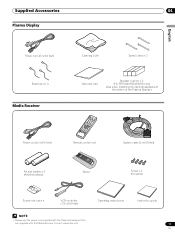
Supplied Accessories 04 Plasma Display English Power cord (2 m/6.6 feet) Bead band × 3 Media Receiver Cleaning cloth Speed clamp × 3 Warranty card Speaker cushion × 3 (For PDP-5045HD/4345HD only) (Use when installing the optional speakers at the bottom of the Plasma Display.) Power cord (2 m/6.6 feet) Remote control unit System cable (3 m/9.8 ...; 4 VCR controller (1.8 m/5.9 feet) Operating Instructions Instruction guide • Always use the power cord supplied with the Plasma Display and the one supplied with the Media Receiver for each respective unit. 11 En
Supplied Accessories 04 Plasma Display English Power cord (2 m/6.6 feet) Bead band × 3 Media Receiver Cleaning cloth Speed clamp × 3 Warranty card Speaker cushion × 3 (For PDP-5045HD/4345HD only) (Use when installing the optional speakers at the bottom of the Plasma Display.) Power cord (2 m/6.6 feet) Remote control unit System cable (3 m/9.8 ...; 4 VCR controller (1.8 m/5.9 feet) Operating Instructions Instruction guide • Always use the power cord supplied with the Plasma Display and the one supplied with the Media Receiver for each respective unit. 11 En
Owner's Manual
Page 12
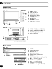
... 10 SYSTEM CABLE terminal (WHITE) 11 SPEAKER (right/left) terminals 12 AC INLET terminal 11 12 The terminals have faced downward. Media Receiver Front view POWER REC DATA ON STANDBY TIMER ACQUISITION 1 2345 Pull this section to open the door. buttons 8 CHANNEL +/- Front...POWER button 2 STANDBY indicator 3 POWER ON indicator 4 Remote control sensor 5 STANDBY/ON button 6 INPUT button 7 VOLUME +/- 05 Part Names Plasma Display Illustrations show PDP-5045HD/4345HD. COMPONENT VIDEO Y CB / PB CR / PR INPUT 4 S-VIDEO VIDEO AUDIO L R AUDIO (STEREO) PC ANALOG RGB 6 7 8 9 10...
... 10 SYSTEM CABLE terminal (WHITE) 11 SPEAKER (right/left) terminals 12 AC INLET terminal 11 12 The terminals have faced downward. Media Receiver Front view POWER REC DATA ON STANDBY TIMER ACQUISITION 1 2345 Pull this section to open the door. buttons 8 CHANNEL +/- Front...POWER button 2 STANDBY indicator 3 POWER ON indicator 4 Remote control sensor 5 STANDBY/ON button 6 INPUT button 7 VOLUME +/- 05 Part Names Plasma Display Illustrations show PDP-5045HD/4345HD. COMPONENT VIDEO Y CB / PB CR / PR INPUT 4 S-VIDEO VIDEO AUDIO L R AUDIO (STEREO) PC ANALOG RGB 6 7 8 9 10...
Owner's Manual
Page 15
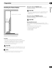
...+40°C (+32°F to sunlight • Under strong artificial light • In high humidity • Poorly ventilated English Illustration shows PDP-5045HD/4345HD. Preparation Installing the Plasma Display Over 50 cm (19 /11 16 inches) Over 10 cm (3 15/ 16 inches ) 06 Using ... This product may result in instability causing possible injury. Using the optional PIONEER speakers For details on the top of the system cable used only with other stands may be used to connect the Plasma Display and the Media Receiver is about 3 m (9.8 feet). • Because the Plasma Display...
...+40°C (+32°F to sunlight • Under strong artificial light • In high humidity • Poorly ventilated English Illustration shows PDP-5045HD/4345HD. Preparation Installing the Plasma Display Over 50 cm (19 /11 16 inches) Over 10 cm (3 15/ 16 inches ) 06 Using ... This product may result in instability causing possible injury. Using the optional PIONEER speakers For details on the top of the system cable used only with other stands may be used to connect the Plasma Display and the Media Receiver is about 3 m (9.8 feet). • Because the Plasma Display...
Owner's Manual
Page 16
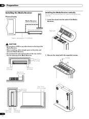
... the stand with the supplied screws. 06 Preparation Installing the Media Receiver Plasma Display Media Receiver (vertical installation) ACQUISITION TIMER STANDBY ON DATA REC POWER Installing the Media Receiver vertically You can use the supplied stand to install the Media Receiver vertically. 1. Screws Over 5 cm (2 inches) Over 5... ACQUISITION Over 5 cm (2 inches) 16 En Over 5 cm (2 inches) Insert the stand into the side of the Media Receiver. (horizontal installation) POWER REC DATA ON STANDBY TIMER ACQUISITION System cable (approx. 3 m/9.8 feet) Right side • Do...
... the stand with the supplied screws. 06 Preparation Installing the Media Receiver Plasma Display Media Receiver (vertical installation) ACQUISITION TIMER STANDBY ON DATA REC POWER Installing the Media Receiver vertically You can use the supplied stand to install the Media Receiver vertically. 1. Screws Over 5 cm (2 inches) Over 5... ACQUISITION Over 5 cm (2 inches) 16 En Over 5 cm (2 inches) Insert the stand into the side of the Media Receiver. (horizontal installation) POWER REC DATA ON STANDBY TIMER ACQUISITION System cable (approx. 3 m/9.8 feet) Right side • Do...

Owner's Manual
Page 17
Remove the separation sheet. They are required when you place the Media Receiver in mechanical failure. 17 En Screw hole cap • When you place the unit directly on the floor, the cooling vents will be sure to use the supplied stand. Plug the screw holes using the supplied caps. If you have installed the Media Receiver vertically, be blocked, resulting in the horizontal position. 4. Preparation 06 3. Align with the hole and attach. Remove the shock absorbing pads. Shock absorbing pad English Keep the shock absorbing pads and screws.
Remove the separation sheet. They are required when you place the Media Receiver in mechanical failure. 17 En Screw hole cap • When you place the unit directly on the floor, the cooling vents will be sure to use the supplied stand. Plug the screw holes using the supplied caps. If you have installed the Media Receiver vertically, be blocked, resulting in the horizontal position. 4. Preparation 06 3. Align with the hole and attach. Remove the shock absorbing pads. Shock absorbing pad English Keep the shock absorbing pads and screws.
Owner's Manual
Page 18
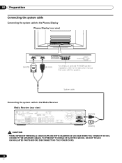
06 Preparation Connecting the system cable Connecting the system cable to the Plasma Display Plasma Display (rear view) (WHITE) (BLACK) For details on optional PIONEER speaker installation, refer to the Media Receiver Media Receiver (rear view) IN OUT VCR CONTROL CONTROL IN ANTENNA B ANTENNA/ CABLE A IN Cable CARD S-VIDEO INPUT 2 VIDEO R-AUDIO-L DIGITAL OUT OPTICAL (TS...
06 Preparation Connecting the system cable Connecting the system cable to the Plasma Display Plasma Display (rear view) (WHITE) (BLACK) For details on optional PIONEER speaker installation, refer to the Media Receiver Media Receiver (rear view) IN OUT VCR CONTROL CONTROL IN ANTENNA B ANTENNA/ CABLE A IN Cable CARD S-VIDEO INPUT 2 VIDEO R-AUDIO-L DIGITAL OUT OPTICAL (TS...
Owner's Manual
Page 21
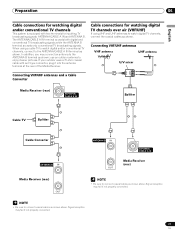
... channels This system is equipped with an F-type connector, plug it into the antenna terminal at the rear of the Media Receiver. Cable connections for inputting TV broadcasting signals: ANTENNA/CABLE A IN and ANTENNA B. When using VHF and UHF antennas ...antennas VHF antenna UHF antenna U/V mixer Connecting VHF/UHF antennas and a Cable Converter Media Receiver (rear) ANTENNA/ CABLE A IN Splitter Cable TV Splitter Cable Converter ANTENNA B IN Media Receiver (rear) OUT ANTENNA B IN OUT ANTENNA/ CABLE A IN Media Receiver (rear) • Be sure to enjoy clearer pictures.
... channels This system is equipped with an F-type connector, plug it into the antenna terminal at the rear of the Media Receiver. Cable connections for inputting TV broadcasting signals: ANTENNA/CABLE A IN and ANTENNA B. When using VHF and UHF antennas ...antennas VHF antenna UHF antenna U/V mixer Connecting VHF/UHF antennas and a Cable Converter Media Receiver (rear) ANTENNA/ CABLE A IN Splitter Cable TV Splitter Cable Converter ANTENNA B IN Media Receiver (rear) OUT ANTENNA B IN OUT ANTENNA/ CABLE A IN Media Receiver (rear) • Be sure to enjoy clearer pictures.

Owner's Manual
Page 22
..., using HTML text. 1 Confirm that the ANTENNA/CABLE A IN terminal has been connected with a slot for Point of Deployment. Inserting the cable card The Media Receiver is equipped with the coaxial cable from the other antenna. • Pressing ANT while watching in the 2-screen mode (TV image and video image) with... antenna A and B To watch broadcasts via the two antennas, you to use the POD service provided by pressing ANT on the rear of the Media Receiver, and remove the cover while releasing the tab's latch. 3 Insert the specified cable card into the Cable CARD slot as far as it by ...
..., using HTML text. 1 Confirm that the ANTENNA/CABLE A IN terminal has been connected with a slot for Point of Deployment. Inserting the cable card The Media Receiver is equipped with the coaxial cable from the other antenna. • Pressing ANT while watching in the 2-screen mode (TV image and video image) with... antenna A and B To watch broadcasts via the two antennas, you to use the POD service provided by pressing ANT on the rear of the Media Receiver, and remove the cover while releasing the tab's latch. 3 Insert the specified cable card into the Cable CARD slot as far as it by ...
Owner's Manual
Page 23
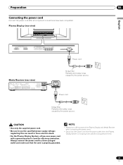
Preparation 06 Connecting the power cord Connect the power cord after all component connections have been completed. Plasma Display (rear view) English Power cord Media Receiver (rear view) IN OUT VCR CONTROL CONTROL IN ANTENNA B ANTENNA/ CABLE A IN Cable CARD S-VIDEO INPUT 2 INPUT 2 VIDEO R-AUDIO-L ...-pronged outlet and make sure that the cord is properly grounded. • Always turn off the power of the Plasma Display and Media Receiver when connecting the power cords. • Disconnect the power cord from the power outlet when the Plasma Display System is used for ...
Preparation 06 Connecting the power cord Connect the power cord after all component connections have been completed. Plasma Display (rear view) English Power cord Media Receiver (rear view) IN OUT VCR CONTROL CONTROL IN ANTENNA B ANTENNA/ CABLE A IN Cable CARD S-VIDEO INPUT 2 INPUT 2 VIDEO R-AUDIO-L ...-pronged outlet and make sure that the cord is properly grounded. • Always turn off the power of the Plasma Display and Media Receiver when connecting the power cords. • Disconnect the power cord from the power outlet when the Plasma Display System is used for ...
Owner's Manual
Page 24
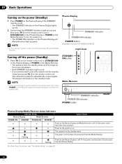
...If you are not going to turn the system on. • The POWER ON indicators on the Plasma Display and Media Receiver light up green. • In this system for a long period of time, press POWER on the Plasma Display ... (Standby) 1 Press TV on the remote control unit or STANDBY/ON on the Plasma Display or POWER on the Media Receiver. • The system enters the standby mode and the image on the screen disappears. • Both STANDBY indicators ... disconnected. Plasma Display STANDBY indicator POWER ON indicator POWER button Illustration shows PDP-5045HD/4345HD. (right view) Turning off .
...If you are not going to turn the system on. • The POWER ON indicators on the Plasma Display and Media Receiver light up green. • In this system for a long period of time, press POWER on the Plasma Display ... (Standby) 1 Press TV on the remote control unit or STANDBY/ON on the Plasma Display or POWER on the Media Receiver. • The system enters the standby mode and the image on the screen disappears. • Both STANDBY indicators ... disconnected. Plasma Display STANDBY indicator POWER ON indicator POWER button Illustration shows PDP-5045HD/4345HD. (right view) Turning off .

Owner's Manual
Page 25
... increase the channel number, press CH + on the Plasma Display operates the same as necessary when in those channels. Using 0 - 9 and • (dot) on the Media Receiver (page 21).
... increase the channel number, press CH + on the Plasma Display operates the same as necessary when in those channels. Using 0 - 9 and • (dot) on the Media Receiver (page 21).
Owner's Manual
Page 32
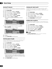
... The Host ID and Cable Card ID appear. 5 Press HOME MENU to exit the menu. Checking the Cable Card ID The Media Receiver has a slot for a cable card that the current signal strength reaches as close to the maximum signal strength as possible. 6.... A Signal Strength Signal Strength Maximum: 100 Current: 100 xxxxxxxxxxxxxxxxxxxxx xxxxxxxxxxxxxxxxxxxxx xxxxxxxxxxxxxxxxxxxxx Home Menu Exit • Adjust the direction of the Media Receiver lights while data is used for antenna B. The following procedure allows you easily identify the channels during selections. 1 Press HOME MENU....
... The Host ID and Cable Card ID appear. 5 Press HOME MENU to exit the menu. Checking the Cable Card ID The Media Receiver has a slot for a cable card that the current signal strength reaches as close to the maximum signal strength as possible. 6.... A Signal Strength Signal Strength Maximum: 100 Current: 100 xxxxxxxxxxxxxxxxxxxxx xxxxxxxxxxxxxxxxxxxxx xxxxxxxxxxxxxxxxxxxxx Home Menu Exit • Adjust the direction of the Media Receiver lights while data is used for antenna B. The following procedure allows you easily identify the channels during selections. 1 Press HOME MENU....
Owner's Manual
Page 39
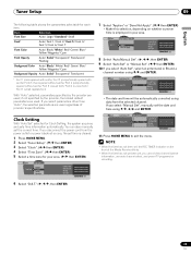
... Clock Setting, the system acquires and sets time information automatically. If you select parameters other than "Auto", the selected parameters are used regardless of the Media Receiver blinks. • When the time has not yet been set the correct time. Clock Auto/Manual Set Auto/Manual Set •Auto Set Clock Set...
... Clock Setting, the system acquires and sets time information automatically. If you select parameters other than "Auto", the selected parameters are used regardless of the Media Receiver blinks. • When the time has not yet been set the correct time. Clock Auto/Manual Set Auto/Manual Set •Auto Set Clock Set...
Owner's Manual
Page 43
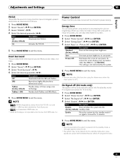
...by decreasing the picture brightness. Energy Save You can also select this function using a new (factory default) technology. This setting is received for 15 minutes. 5 Press HOME MENU to save power. Enable Places the system into the standby mode if no signal is ...Select "Enable". ( / then ENTER) Item Description Disable Does not place the system into the standby mode when noise signals are present at the Media Receiver after a TV program finishes. 43 En TruBass Provides deep, rich bass using the Home menu when the input source is incorporated under license from ...
...by decreasing the picture brightness. Energy Save You can also select this function using a new (factory default) technology. This setting is received for 15 minutes. 5 Press HOME MENU to save power. Enable Places the system into the standby mode if no signal is ...Select "Enable". ( / then ENTER) Item Description Disable Does not place the system into the standby mode when noise signals are present at the Media Receiver after a TV program finishes. 43 En TruBass Provides deep, rich bass using the Home menu when the input source is incorporated under license from ...
Owner's Manual
Page 45
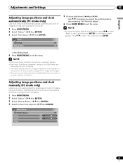
... Adjust Clock 0 Phase 0 Reset 45 En If not successful, change the PC image and try again. • Be sure to connect the computer to the Media Receiver and switch it on conditions. • Auto Setup may have failed, depending on before starting Auto Setup. appears. • Even when "Auto Setup completed." A confirmation...
... Adjust Clock 0 Phase 0 Reset 45 En If not successful, change the PC image and try again. • Be sure to connect the computer to the Media Receiver and switch it on conditions. • Auto Setup may have failed, depending on before starting Auto Setup. appears. • Even when "Auto Setup completed." A confirmation...

Owner's Manual
Page 49
... for auto channel select. Rule 3: If presettings at the same start time are overlapped, presetting with a VCR, confirm that the video output terminals on the Media Receiver have been connected to the signal input terminals on the recording equipment at the exact start of the program; This is also true when a specified...
... for auto channel select. Rule 3: If presettings at the same start time are overlapped, presetting with a VCR, confirm that the video output terminals on the Media Receiver have been connected to the signal input terminals on the recording equipment at the exact start of the program; This is also true when a specified...


