
Owner's Manual
Page 1
.... LTD. 253 Alexandra Road, #04-01, Singapore 159936 TEL: 65-6472-7555 PIONEER ELECTRONICS AUSTRALIA PTY. Universal Rear View Camera Caméra de recul universelle Owner's Manual Mode d'emploi ND-BC2 PIONEER CORPORATION 4-1, MEGURO 1-CHOME, MEGURO-KU, TOKYO 153-8654, JAPAN PIONEER ELECTRONICS (USA) INC. LTD. 178-184 Boundary Road, Braeside, Victoria 3195, Australia TEL: (03) 9586...
.... LTD. 253 Alexandra Road, #04-01, Singapore 159936 TEL: 65-6472-7555 PIONEER ELECTRONICS AUSTRALIA PTY. Universal Rear View Camera Caméra de recul universelle Owner's Manual Mode d'emploi ND-BC2 PIONEER CORPORATION 4-1, MEGURO 1-CHOME, MEGURO-KU, TOKYO 153-8654, JAPAN PIONEER ELECTRONICS (USA) INC. LTD. 178-184 Boundary Road, Braeside, Victoria 3195, Australia TEL: (03) 9586...
Owner's Manual
Page 2
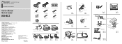
... back of charge to designated collection facilities or to a retailer (if you will ensure that there is a rear view camera for the rear view camera cable to install the rear view camera. Do not drill into the gas line, brake line, electrical wiring or other dirt from the side of ...propio objetivo de la cámara con un encendedor o algo similar cuando los mismos estén congelados. Installing Using Camera Stand Bracket (Fig. 11-4) 1. Attach the camera stand and rear view camera. (Fig. 3-4) Route the cables as the above , please contact your car's shape or the installation site. ...
... back of charge to designated collection facilities or to a retailer (if you will ensure that there is a rear view camera for the rear view camera cable to install the rear view camera. Do not drill into the gas line, brake line, electrical wiring or other dirt from the side of ...propio objetivo de la cámara con un encendedor o algo similar cuando los mismos estén congelados. Installing Using Camera Stand Bracket (Fig. 11-4) 1. Attach the camera stand and rear view camera. (Fig. 3-4) Route the cables as the above , please contact your car's shape or the installation site. ...
Owner's Manual
Page 6
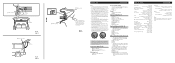
.... Do not route wiring in . Connection sample (Fig. 14) ① Power supply unit ② Rear view camera connector ③ RCA power supply cable connector ④ Rear view camera Video input jack Connect to video input jack. ⑤ RCA pin Accessory power supply To electric terminal controlled... feed power to other equipment by cutting the insu- ① Pull out from here ② Hinge ③ Harness cover ④ Rear view camera ⑤ Hatch ① Rear view camera Fig. 16 Abb. 16 ② Hatch ③ Cord Fig. 17 Abb. 17 ① Clamps ③ Rubber packing ②...
.... Do not route wiring in . Connection sample (Fig. 14) ① Power supply unit ② Rear view camera connector ③ RCA power supply cable connector ④ Rear view camera Video input jack Connect to video input jack. ⑤ RCA pin Accessory power supply To electric terminal controlled... feed power to other equipment by cutting the insu- ① Pull out from here ② Hinge ③ Harness cover ④ Rear view camera ⑤ Hatch ① Rear view camera Fig. 16 Abb. 16 ② Hatch ③ Cord Fig. 17 Abb. 17 ① Clamps ③ Rubber packing ②...
