Owner's Manual
Page 2
Contents Before you start Information to User 3 After-sales service for Pioneer products 3 Visit our website 3 Before connecting/installing the amplifier 4 Setting the Unit What's what 5 Setting gain properly 5 Connecting the units Connection diagram 7 Before connecting the amplifier 7 About bridged mode 8 About suitable specification of speaker 8 Connecting the speakers 8 Connections when using the speaker...
Contents Before you start Information to User 3 After-sales service for Pioneer products 3 Visit our website 3 Before connecting/installing the amplifier 4 Setting the Unit What's what 5 Setting gain properly 5 Connecting the units Connection diagram 7 Before connecting the amplifier 7 About bridged mode 8 About suitable specification of speaker 8 Connecting the speakers 8 Connections when using the speaker...
Owner's Manual
Page 4
...gine is recommended. Also, damage to cause cancer and birth defects or other reproductive harm. The surfaces of the amplifier and any abnormality, the power supply to the amplifier is located on proposition 65 known to avoid the risk of this product or cords as- Always disconnect the negative ...attached speakers may exhaust the battery. If you to record this number on this unit. CAUTION ! sociated with accessories sold battery wire or the amplifier fuse blows. Important (Serial number) The serial number is cut off to the car body. ! Wash hands after handling. ! Do not ...
...gine is recommended. Also, damage to cause cancer and birth defects or other reproductive harm. The surfaces of the amplifier and any abnormality, the power supply to the amplifier is located on proposition 65 known to avoid the risk of this product or cords as- Always disconnect the negative ...attached speakers may exhaust the battery. If you to record this number on this unit. CAUTION ! sociated with accessories sold battery wire or the amplifier fuse blows. Important (Serial number) The serial number is cut off to the car body. ! Wash hands after handling. ! Do not ...
Owner's Manual
Page 5
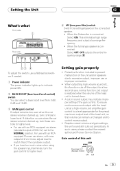
... and outputs low range frequency. ! To adjust the switch, use with an RCA equipped car stereo (standard output of 500 mV), set amplifier gain control to a level appropriate for a few seconds as a normal function, but output is restored when the volume of the head unit... the speaker input terminals, turn these controls to control excess output. ! Setting gain properly ! In such cases, please contact the nearest authorized Pioneer Service Station. Despite correct volume and gain settings, the unit sound still cuts out periodically. For use a flathead screwdriver if needed. 1 Power...
... and outputs low range frequency. ! To adjust the switch, use with an RCA equipped car stereo (standard output of 500 mV), set amplifier gain control to a level appropriate for a few seconds as a normal function, but output is restored when the volume of the head unit... the speaker input terminals, turn these controls to control excess output. ! Setting gain properly ! In such cases, please contact the nearest authorized Pioneer Service Station. Despite correct volume and gain settings, the unit sound still cuts out periodically. For use a flathead screwdriver if needed. 1 Power...
Owner's Manual
Page 6
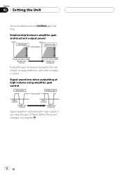
Section 02 Setting the Unit Above illustration shows NORMAL gain setting. Relationship between amplifier gain and head unit output power If amplifier gain is raised improperly, this will simply increase distortion, with high output, if you raise the gain of the amplifier the power changes only slightly. 6 En Signal waveform when outputting at high volume using amplifier gain control Signal waveform distorted with little increase in power.
Section 02 Setting the Unit Above illustration shows NORMAL gain setting. Relationship between amplifier gain and head unit output power If amplifier gain is raised improperly, this will simply increase distortion, with high output, if you raise the gain of the amplifier the power changes only slightly. 6 En Signal waveform when outputting at high volume using amplifier gain control Signal waveform distorted with little increase in power.
Owner's Manual
Page 7
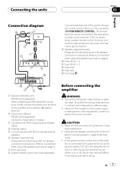
...223 (sold separately) After completing all other equipment. gether multiple speakers' negative (*) lead wires. ! If the system remote control wire of the amplifier to the positive (+) battery terminal. 2 Ground wire (Black) RD-223 (sold separately) Connect to metal body or chassis. 3 Car stereo... with RCA output jacks (sold separately) Before connecting the amplifier WARNING ! Connecting the units Section 03 English Connection diagram Connect male terminal of this wire to the system remote control terminal of the...
...223 (sold separately) After completing all other equipment. gether multiple speakers' negative (*) lead wires. ! If the system remote control wire of the amplifier to the positive (+) battery terminal. 2 Ground wire (Black) RD-223 (sold separately) Connect to metal body or chassis. 3 Car stereo... with RCA output jacks (sold separately) Before connecting the amplifier WARNING ! Connecting the units Section 03 English Connection diagram Connect male terminal of this wire to the system remote control terminal of the...
Owner's Manual
Page 8
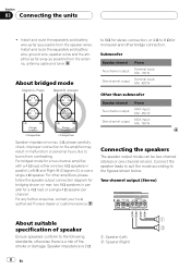
For any further enquiries, contact your local authorized Pioneer dealer or customer service. Speaker impedance is max. 4 W, please carefully check. Subwoofer Speaker channel Two-channel output One-channel output Power Nominal input: Min. 135 W ... a 4 W load, either wire two 8 W speakers in malfunction or personal injury due to the figures shown below. Improper connection to the amplifier may result in parallel, Left + and Right * (Diagram A) or use a single 4 W speaker. Connecting the speakers The speaker output mode can be two-channel (stereo) or ...
For any further enquiries, contact your local authorized Pioneer dealer or customer service. Speaker impedance is max. 4 W, please carefully check. Subwoofer Speaker channel Two-channel output One-channel output Power Nominal input: Min. 135 W ... a 4 W load, either wire two 8 W speakers in malfunction or personal injury due to the figures shown below. Improper connection to the amplifier may result in parallel, Left + and Right * (Diagram A) or use a single 4 W speaker. Connecting the speakers The speaker output mode can be two-channel (stereo) or ...
Owner's Manual
Page 9
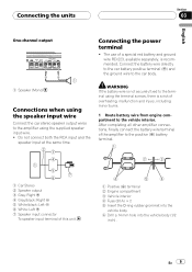
... battery wire is not securely fixed to the terminal using the supplied speaker input wire. ! After completing all other amplifier connections, finally connect the battery wire terminal of the amplifier to the positive (+) battery terminal. 1 Car Stereo 2 Speaker output 3 Gray: Right + 4 Gray/black: ...To speaker input terminal of overheating, malfunction and injury, including minor burns. 1 Route battery wire from engine compartment to the amplifier using the terminal screws, there is recommended. En 9 Connecting the units Section 03 English One-channel output Connecting the power ...
... battery wire is not securely fixed to the terminal using the supplied speaker input wire. ! After completing all other amplifier connections, finally connect the battery wire terminal of the amplifier to the positive (+) battery terminal. 1 Car Stereo 2 Speaker output 3 Gray: Right + 4 Gray/black: ...To speaker input terminal of overheating, malfunction and injury, including minor burns. 1 Route battery wire from engine compartment to the amplifier using the terminal screws, there is recommended. En 9 Connecting the units Section 03 English One-channel output Connecting the power ...
Owner's Manual
Page 12
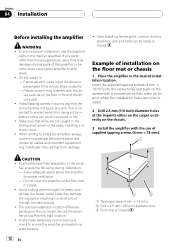
... in a short-circuit. ! fuel/brake lines, wiring) from being cut by vibration of the seats, resulting in front of the amplifier, or become loose causing the amplifier to ensure the amplifier and system operate properly. 12 En 1 Tapping-screws (4 mm × 18 mm) 2 Drill a 2.5 mm (1/8 inch) diameter... To ensure proper heat dissipation of supplied tapping screws (4 mm × 18 mm). Do not cover the amplifier with the dri- Section 04 Installation Before installing the amplifier WARNING ! To ensure proper installation, use of the ampli- If any wire. Places where it could injure...
... in a short-circuit. ! fuel/brake lines, wiring) from being cut by vibration of the seats, resulting in front of the amplifier, or become loose causing the amplifier to ensure the amplifier and system operate properly. 12 En 1 Tapping-screws (4 mm × 18 mm) 2 Drill a 2.5 mm (1/8 inch) diameter... To ensure proper heat dissipation of supplied tapping screws (4 mm × 18 mm). Do not cover the amplifier with the dri- Section 04 Installation Before installing the amplifier WARNING ! To ensure proper installation, use of the ampli- If any wire. Places where it could injure...
Owner's Manual
Page 13
The average current drawn is nearly the maximum current drawn by multiple power amplifiers. En 13 Specifications and the design are subject to modifications without notice due to 26 V Maximum input level / impedance: RCA 6.5 V / 22 kW Speaker 26 V / 90 ...
The average current drawn is nearly the maximum current drawn by multiple power amplifiers. En 13 Specifications and the design are subject to modifications without notice due to 26 V Maximum input level / impedance: RCA 6.5 V / 22 kW Speaker 26 V / 90 ...

