Owner's Manual
Page 2
... from where you have any other information. Box 1760 Long Beach, CA 90801-1760 800-421-1404 7 CANADA Pioneer Electronics of Canada, Inc. PIONEER SUGGESTS USING A PROFESSIONAL INSTALLER DUE TO THE COMPLEXITY OF THIS PRODUCT. It is not available, please contact the ...the Power Terminal 8 Connecting the Speaker Output Terminals ...... 9 Using the Speaker Input 9 Connecting the Speaker Wires 9 Installation 10 Attaching the Bass boost remote control ........ 11 Example of installation on the floor mat or on the chassis 11 Specifications 12 Thank you for purchasing this manual before ...
... from where you have any other information. Box 1760 Long Beach, CA 90801-1760 800-421-1404 7 CANADA Pioneer Electronics of Canada, Inc. PIONEER SUGGESTS USING A PROFESSIONAL INSTALLER DUE TO THE COMPLEXITY OF THIS PRODUCT. It is not available, please contact the ...the Power Terminal 8 Connecting the Speaker Output Terminals ...... 9 Using the Speaker Input 9 Connecting the Speaker Wires 9 Installation 10 Attaching the Bass boost remote control ........ 11 Example of installation on the floor mat or on the chassis 11 Specifications 12 Thank you for purchasing this manual before ...
Owner's Manual
Page 5
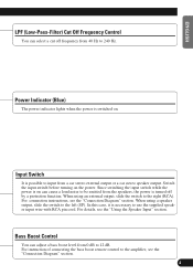
Input Switch It is possible to the amplifier, see the "Connection Diagram" section. 4 Switch the input switch before turning on can cause a loud noise to be emitted from the speakers, the power is on the power. For instruction of connecting the bass boost remote control to input from 0 dB to the right (RCA).... Since switching the input switch while the power is turned off frequency from 40 Hz to 240 Hz. In this case, it is switched on. When using an external output, slide the switch to 12 dB. Bass Boost ...
Input Switch It is possible to the amplifier, see the "Connection Diagram" section. 4 Switch the input switch before turning on can cause a loud noise to be emitted from the speakers, the power is on the power. For instruction of connecting the bass boost remote control to input from 0 dB to the right (RCA).... Since switching the input switch while the power is turned off frequency from 40 Hz to 240 Hz. In this case, it is switched on. When using an external output, slide the switch to 12 dB. Bass Boost ...
Owner's Manual
Page 8
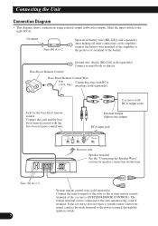
...the male terminal of this jack and the bass boost remote control with RCA (19 ft. 8in.) pin plugs (sold separately) After making all other connections at the amplifier, connect the battery wire terminal of the amplifier to the auto-antenna relay control terminal.... Fuse (30 A) × 2 7 System remote control wire (sold separately) Connect to the system remote control terminal of the battery. Bass Boost Remote Control Wire 6 m Connecting wire with the bass boost remote...
...the male terminal of this jack and the bass boost remote control with RCA (19 ft. 8in.) pin plugs (sold separately) After making all other connections at the amplifier, connect the battery wire terminal of the amplifier to the auto-antenna relay control terminal.... Fuse (30 A) × 2 7 System remote control wire (sold separately) Connect to the system remote control terminal of the battery. Bass Boost Remote Control Wire 6 m Connecting wire with the bass boost remote...
Owner's Manual
Page 12
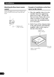
... it is to be located. 2. Push on the screws with tapping screws (3 mm × 10 mm) at the point marked, and install the amplifier, either on the chassis 1. Tapping screw (3 mm × 10 mm) Example of installation on the floor mat or on the carpet or directly to the ... the supplied tapping screws (4 mm × 18 mm) into the screw holes. Drill 2.5 mm (1/8 in .) diameter hole Floor mat or chassis 11 Installation Attaching the Bass boost remote control Attach with a screwdriver so they make marks where the installation holes are to be installed.
... it is to be located. 2. Push on the screws with tapping screws (3 mm × 10 mm) at the point marked, and install the amplifier, either on the chassis 1. Tapping screw (3 mm × 10 mm) Example of installation on the floor mat or on the carpet or directly to the ... the supplied tapping screws (4 mm × 18 mm) into the screw holes. Drill 2.5 mm (1/8 in .) diameter hole Floor mat or chassis 11 Installation Attaching the Bass boost remote control Attach with a screwdriver so they make marks where the installation holes are to be installed.


