Owners Manual
Page 1
... with Left + and Right - (Diagram A) or use a single 4 Ω speaker per channel. BRIDGEABLE TWO-CHANNEL POWER AMPLIFIER AMPLIFICATEUR DE PUISSANCE PONTABLE A DEUX VOIES Owner's Manual GM-3100T Mode d'emploi PIONEER CORPORATION 4-1, MEGURO 1-CHOME, MEGURO-KU, TOKYO 153-8654, JAPAN PIONEER ELECTRONICS (USA) INC. In case the necessary information is designed to operate the equipment. Also...
... with Left + and Right - (Diagram A) or use a single 4 Ω speaker per channel. BRIDGEABLE TWO-CHANNEL POWER AMPLIFIER AMPLIFICATEUR DE PUISSANCE PONTABLE A DEUX VOIES Owner's Manual GM-3100T Mode d'emploi PIONEER CORPORATION 4-1, MEGURO 1-CHOME, MEGURO-KU, TOKYO 153-8654, JAPAN PIONEER ELECTRONICS (USA) INC. In case the necessary information is designed to operate the equipment. Also...
Owners Manual
Page 2
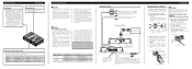
... the heater will be connected to match the car stereo output level. • If you hear too much noise when using with an RCA equipped Pioneer car stereo with max. input: Min. 120 W Nominal input: Min. 180 W Max. The female terminal can be exceeded, causing overheating. &#... Speaker wire System remote control wire Ground wire Battery wire When using the speaker input terminals, turn gain control on the front of the power amplifier clockwise. input: Min. 300 W Connection Diagram Fuse (30 A) Grommet Fuse (30 A) Special red battery wire [RD-223] (sold separately) Connect ...
... the heater will be connected to match the car stereo output level. • If you hear too much noise when using with an RCA equipped Pioneer car stereo with max. input: Min. 120 W Nominal input: Min. 180 W Max. The female terminal can be exceeded, causing overheating. &#... Speaker wire System remote control wire Ground wire Battery wire When using the speaker input terminals, turn gain control on the front of the power amplifier clockwise. input: Min. 300 W Connection Diagram Fuse (30 A) Grommet Fuse (30 A) Special red battery wire [RD-223] (sold separately) Connect ...
Owners Manual
Page 3
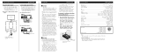
...to be easily removed. Electrical shock could result. Drill 2.5 mm (1/8 inch) diameter holes at the point marked, and install the amplifier, either on unstable places such as fuel lines, brake lines and electrical wiring from being cut by vibration of this unit when an .... Tapping-screws (4 × 18 mm) CAUTION: To prevent malfunction and/or injury • To ensure proper heat dissipation of the amplifier, be located. 2. Also, amplifier and speaker damage, smoke, and overheating could injure the driver or passengers if the vehicle stops suddenly. -Places where it is input....
...to be easily removed. Electrical shock could result. Drill 2.5 mm (1/8 inch) diameter holes at the point marked, and install the amplifier, either on unstable places such as fuel lines, brake lines and electrical wiring from being cut by vibration of this unit when an .... Tapping-screws (4 × 18 mm) CAUTION: To prevent malfunction and/or injury • To ensure proper heat dissipation of the amplifier, be located. 2. Also, amplifier and speaker damage, smoke, and overheating could injure the driver or passengers if the vehicle stops suddenly. -Places where it is input....

