
Owner's Manual
Page 7
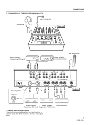
Connection of Outputs, Microphones, Etc. Headphone Main microphone DJM-500 CONNECTIONS Power amplifier (Supporting RCA input) Sub microphone Power amplifier (For booth monitor) R L L R MASTER BOOTH OUT 1 MONITOR L CH - 4 PHONO 3 CH -...OUT 2 R LR LR L CH - 4 L MASTER OUT 3 SEND (MONO) RETURN (MONO) SUBMIC Pin assignment *1 DJM-500 COLD (-) 23 1 HOT (+) GND Power amplifier Power amplifier External effector (Supporting XLR input) (Supporting PHONE input) *1 Master level attenuator knob To protect the connected amplifiers and speakers from excessive inputs, this...
Connection of Outputs, Microphones, Etc. Headphone Main microphone DJM-500 CONNECTIONS Power amplifier (Supporting RCA input) Sub microphone Power amplifier (For booth monitor) R L L R MASTER BOOTH OUT 1 MONITOR L CH - 4 PHONO 3 CH -...OUT 2 R LR LR L CH - 4 L MASTER OUT 3 SEND (MONO) RETURN (MONO) SUBMIC Pin assignment *1 DJM-500 COLD (-) 23 1 HOT (+) GND Power amplifier Power amplifier External effector (Supporting XLR input) (Supporting PHONE input) *1 Master level attenuator knob To protect the connected amplifiers and speakers from excessive inputs, this...

Owner's Manual
Page 9
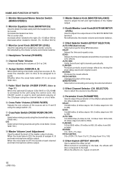
1 Main Microphone Terminal and Microphone Control Knob MIC Level: Used for adjusting the volume of the main microphone. (Attenuated level -∞ to 0 dB) HI: Used for adjusting the high tone of the ... +12 dB at 100 Hz) Decreases when rotated to the left. (To -12 dB at 100 Hz) 2 CH1 to CH4 Input Selection Switch and Control Knob/Peak level meter Input selection switch: Selects which beat the parameter is set. (1/2 to Page 14.) • When BPM is selected.) The counter displays the...
1 Main Microphone Terminal and Microphone Control Knob MIC Level: Used for adjusting the volume of the main microphone. (Attenuated level -∞ to 0 dB) HI: Used for adjusting the high tone of the ... +12 dB at 100 Hz) Decreases when rotated to the left. (To -12 dB at 100 Hz) 2 CH1 to CH4 Input Selection Switch and Control Knob/Peak level meter Input selection switch: Selects which beat the parameter is set. (1/2 to Page 14.) • When BPM is selected.) The counter displays the...
Owner's Manual
Page 10
... the beat. PITCH SHIFTER: Changes the pitch of CH1 to produce the echo effects. SELECTOR) Use to select the source to be output. ^ Master Balance Knob (MASTER BALANCE) Used to adjust the left and right channels periodically. Flat at 100 Hz) - Not affected by the master volume and master balance. = Headphone... fader switch ($) is on (cross fader mix). @ Fader Start Switch (FADER START) (Refer to Page 17.) When the optional CD player (CDJ-500G or CDJ-500 ) is connected to the unit using the control cord, this ON/OFF switch is on, it goes on and off . REVERB: Produces the reverb effects...
... the beat. PITCH SHIFTER: Changes the pitch of CH1 to produce the echo effects. SELECTOR) Use to select the source to be output. ^ Master Balance Knob (MASTER BALANCE) Used to adjust the left and right channels periodically. Flat at 100 Hz) - Not affected by the master volume and master balance. = Headphone... fader switch ($) is on (cross fader mix). @ Fader Start Switch (FADER START) (Refer to Page 17.) When the optional CD player (CDJ-500G or CDJ-500 ) is connected to the unit using the control cord, this ON/OFF switch is on, it goes on and off . REVERB: Produces the reverb effects...
Owner's Manual
Page 11
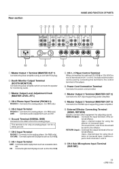
...can be used by connecting this terminal to the analog player. (for MM only) CD/LINE : Connects optional CD players such as CDJ-500 . 8 CH-1 Input Terminal LINE : Connects audio equipment such as DAT. 6 Ground Terminal (SIGNAL GND) Connects to connect other equipment ... cord with RCA plug. 2 Booth Monitor Output Terminal (BOOTH MONITOR) Connects the power amplifier which connects the speaker for monitoring audio. 3 Master Output Level Adjustment Knob (MASTER LEVEL ATT.) 4 CH-4 Phono Input Terminal (PHONO 3) PHONO 3 : Connects the analog player. (for MM only) 5 CH-3 Input Terminal PHONO ...
...can be used by connecting this terminal to the analog player. (for MM only) CD/LINE : Connects optional CD players such as CDJ-500 . 8 CH-1 Input Terminal LINE : Connects audio equipment such as DAT. 6 Ground Terminal (SIGNAL GND) Connects to connect other equipment ... cord with RCA plug. 2 Booth Monitor Output Terminal (BOOTH MONITOR) Connects the power amplifier which connects the speaker for monitoring audio. 3 Master Output Level Adjustment Knob (MASTER LEVEL ATT.) 4 CH-4 Phono Input Terminal (PHONO 3) PHONO 3 : Connects the analog player. (for MM only) 5 CH-3 Input Terminal PHONO ...
Owner's Manual
Page 12
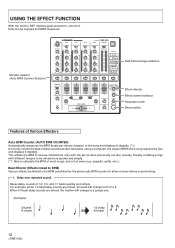
...to be enjoyed and BPM measured. Monitor selector (Auto BPM Counter Selector) MIC CH-1 CD 1/LINE LINE PROFESSIONAL CH-2 CH-3 DJ MIXER DJM-500 CH-4 MASTER CD 2/LINE PHONO 1 LINE PHONO 2 SUB MIC PHONO 3 MONO STEREO POWER MIC LEVEL -∞ 0dB HI -12dB +12dB...BALANCE PARAMETER L R BOOTH MONITOR LEVEL MIN MAX EFFECT ON/OFF -∞ 0dB Real-time/average selection Effect selector Effect channel selector Parameter knob Effect switch Features of Various Effectors Auto BPM Counter (AUTO BPM COUNTER) Automatically measures the BPM (beats per minute (tempo)) of the ...
...to be enjoyed and BPM measured. Monitor selector (Auto BPM Counter Selector) MIC CH-1 CD 1/LINE LINE PROFESSIONAL CH-2 CH-3 DJ MIXER DJM-500 CH-4 MASTER CD 2/LINE PHONO 1 LINE PHONO 2 SUB MIC PHONO 3 MONO STEREO POWER MIC LEVEL -∞ 0dB HI -12dB +12dB...BALANCE PARAMETER L R BOOTH MONITOR LEVEL MIN MAX EFFECT ON/OFF -∞ 0dB Real-time/average selection Effect selector Effect channel selector Parameter knob Effect switch Features of Various Effectors Auto BPM Counter (AUTO BPM COUNTER) Automatically measures the BPM (beats per minute (tempo)) of the ...
Owner's Manual
Page 14
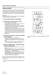
...) will show the BPM (value). 3 Press CH2 of the monitor selector (auto BPM counter selector). • The auto BPM counter LED 2 lights up . (*1) * The parameter knob does not operate in BPM measuring mode. 1234 AUTO BPM COUNTER BPM REAL AVERAGE MASTER 1 2 3 4 MIC PARAMETER BPM 1/2 3/4 1/1 2/1 4/1 BEAT *1 Display when BPM of CH2 (126...
...) will show the BPM (value). 3 Press CH2 of the monitor selector (auto BPM counter selector). • The auto BPM counter LED 2 lights up . (*1) * The parameter knob does not operate in BPM measuring mode. 1234 AUTO BPM COUNTER BPM REAL AVERAGE MASTER 1 2 3 4 MIC PARAMETER BPM 1/2 3/4 1/1 2/1 4/1 BEAT *1 Display when BPM of CH2 (126...
Owner's Manual
Page 15
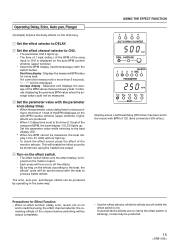
... the effect switch is displayed on the auto BPM counter window (upper window). • Select the BPM display (real-time/average) with the parameter knob (delay time). • When the parameter value (delay time) is set according to the time of 1 beat of the BPM displayed on the auto...turn on or off (while the effect switch is imposed on the master output. Average display : Measures and displays the average of 120 (time conversion 500 mSec.) Precautions for every beat. Each press will not light up . Real-time display : Displays the measured BPM value for Effect Function •...
... the effect switch is displayed on the auto BPM counter window (upper window). • Select the BPM display (real-time/average) with the parameter knob (delay time). • When the parameter value (delay time) is set according to the time of 1 beat of the BPM displayed on the auto...turn on or off (while the effect switch is imposed on the master output. Average display : Measures and displays the average of 120 (time conversion 500 mSec.) Precautions for every beat. Each press will not light up . Real-time display : Displays the measured BPM value for Effect Function •...
Owner's Manual
Page 16
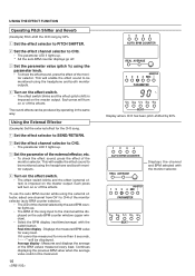
... value could not be displayed on the master output. The reverb effects can be displayed. To use the auto BPM counter while using the parameter knob. • To check the effect sound, press the effect of the monitor selector. Average display : Measures and displays the average of the song input to...
... value could not be displayed on the master output. The reverb effects can be displayed. To use the auto BPM counter while using the parameter knob. • To check the effect sound, press the effect of the monitor selector. Average display : Measures and displays the average of the song input to...
Owner's Manual
Page 18
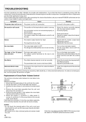
...8226; The fader start switch is something wrong with this component, check the points below , ask your nearest PIONEER authorized service center or your nearest dealer or PIONEER authorized service center. does not start switch. • Connect the control terminals of the cross fader in ... cross fader assembly. Investigate the other external interference. Sometimes the trouble may be imposed with the effects properly. • Adjust the parameter knob. Noises • The master output level is too high. • The input level is set too low. • Select the ...
...8226; The fader start switch is something wrong with this component, check the points below , ask your nearest PIONEER authorized service center or your nearest dealer or PIONEER authorized service center. does not start switch. • Connect the control terminals of the cross fader in ... cross fader assembly. Investigate the other external interference. Sometimes the trouble may be imposed with the effects properly. • Adjust the parameter knob. Noises • The master output level is too high. • The input level is set too low. • Select the ...

