
Owner's Manual
Page 1
... PARTS 8 Front section 8 Rear section 11 USING THE EFFECT FUNCTION 12 Features of Input Equipment 6 2. To prevent electromagnetic interference with electric appliances such as radios and televisions, use shielded cables and connectors for buying this Pioneer product. MODEL NO. IMPORTANT NOTICE: RECORD THE MODEL NUMBER AND SERIAL NUMBER OF THIS EQUIPMENT BELOW. DJM-500...
... PARTS 8 Front section 8 Rear section 11 USING THE EFFECT FUNCTION 12 Features of Input Equipment 6 2. To prevent electromagnetic interference with electric appliances such as radios and televisions, use shielded cables and connectors for buying this Pioneer product. MODEL NO. IMPORTANT NOTICE: RECORD THE MODEL NUMBER AND SERIAL NUMBER OF THIS EQUIPMENT BELOW. DJM-500...
Owner's Manual
Page 2
...DISCHARGE UNIT (NEC SECTION 810 - 20) GROUNDING CONDUCTORS (NEC SECTION 810 - 21) GROUND CLAMPS POWER SERVICE GROUNDING ELECTRODE SYSTEM (NEC ART 250, PART H) [For Canadian model] This Class B digital apparatus meets all requirements of the grounding-type plug. This plug will only fit into the appliance....All warnings on a bed, sofa, rug, or similar surface that they exit from heat sources such as marked on or pinched by a Pioneer authorized service center or qualified service personnel when: ÷ The power-supply cord or the plug has been damaged. ÷ Objects have fallen...
...DISCHARGE UNIT (NEC SECTION 810 - 20) GROUNDING CONDUCTORS (NEC SECTION 810 - 21) GROUND CLAMPS POWER SERVICE GROUNDING ELECTRODE SYSTEM (NEC ART 250, PART H) [For Canadian model] This Class B digital apparatus meets all requirements of the grounding-type plug. This plug will only fit into the appliance....All warnings on a bed, sofa, rug, or similar surface that they exit from heat sources such as marked on or pinched by a Pioneer authorized service center or qualified service personnel when: ÷ The power-supply cord or the plug has been damaged. ÷ Objects have fallen...
Owner's Manual
Page 3
... undetectable until you can radiate radio frequency energy and, if not installed and used in accordance with the limits for a Class B digital device, pursuant to Part 15 of your equipment by playing it at a safe level. Reorient or relocate the receiving antenna. - Consult the dealer or an experienced radio/TV technician...
... undetectable until you can radiate radio frequency energy and, if not installed and used in accordance with the limits for a Class B digital device, pursuant to Part 15 of your equipment by playing it at a safe level. Reorient or relocate the receiving antenna. - Consult the dealer or an experienced radio/TV technician...

Owner's Manual
Page 8
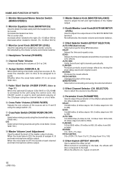
NAME AND FUNCTION OF PARTS Front section 1 2 3 45 8 9 0 - = MIC CH-1 CD 1/LINE LINE PROFESSIONAL CH-2 CH-3 DJ MIXER DJM-500 CH-4 MASTER CD 2/LINE PHONO 1 LINE PHONO 2 SUB MIC PHONO 3 MONO STEREO POWER MIC LEVEL -∞ 0dB HI -12dB +12dB MID EQ -12dB +12dB LOW -...
NAME AND FUNCTION OF PARTS Front section 1 2 3 45 8 9 0 - = MIC CH-1 CD 1/LINE LINE PROFESSIONAL CH-2 CH-3 DJ MIXER DJM-500 CH-4 MASTER CD 2/LINE PHONO 1 LINE PHONO 2 SUB MIC PHONO 3 MONO STEREO POWER MIC LEVEL -∞ 0dB HI -12dB +12dB MID EQ -12dB +12dB LOW -...

Owner's Manual
Page 9
... is about -24 dB to +14 dB. If it could be turned on. 3 Master Output Monaural/Stereo Selection Switch (MONO/STEREO) NAME AND FUNCTION OF PARTS 4 Master level meter (MASTER LEVEL) Displays the output level after master volume adjusment while holding it for more than BPM is selected using the effect...
... is about -24 dB to +14 dB. If it could be turned on. 3 Master Output Monaural/Stereo Selection Switch (MONO/STEREO) NAME AND FUNCTION OF PARTS 4 Master level meter (MASTER LEVEL) Displays the output level after master volume adjusment while holding it for more than BPM is selected using the effect...
Owner's Manual
Page 10
...switch ($) is on (cross fader mix). @ Fader Start Switch (FADER START) (Refer to Page 17.) When the optional CD player (CDJ-500G or CDJ-500 ) is connected to the unit using the cross fader. (Cross fader mix.) % Master Volume Level Adjustment Used to A and B. Not affected by mixing the...2% step from 10 to 100) _ Effect Switch (EFFECT ON/OFF) Use to obtain the beat easily with the effect selector switch. NAME AND FUNCTION OF PARTS 9 Monitor Monaural/Stereo Selector Switch (MONO/STEREO) 0 Monitor Equalizer Knob (MONITOR EQ) Used to switch the effect on/off . 10 PITCH SHIFTER: Changes ...
...switch ($) is on (cross fader mix). @ Fader Start Switch (FADER START) (Refer to Page 17.) When the optional CD player (CDJ-500G or CDJ-500 ) is connected to the unit using the cross fader. (Cross fader mix.) % Master Volume Level Adjustment Used to A and B. Not affected by mixing the...2% step from 10 to 100) _ Effect Switch (EFFECT ON/OFF) Use to obtain the beat easily with the effect selector switch. NAME AND FUNCTION OF PARTS 9 Monitor Monaural/Stereo Selector Switch (MONO/STEREO) 0 Monitor Equalizer Knob (MONITOR EQ) Used to switch the effect on/off . 10 PITCH SHIFTER: Changes ...
Owner's Manual
Page 11
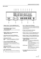
...MM only) CD/LINE : Connects optional CD players such as CDJ-500 . 8 CH-1 Input Terminal LINE : Connects audio equipment such as the CDJ-500 . 9 CH-1, 2 Player Control Terminal When connecting the optional CDJ-500 or CDJ-500G to the CD terminals of CH-1 or CH-2,... OUT 3) Connects the PHONE input supporting power amplifier. ~ External Effector Connecting Terminal (SEND, RETURN) Used to both channels L and R. ! Rear section NAME AND FUNCTION OF PARTS 1 23 4 5 6 7 9 8 9 MASTER BOOTH OUT 1 MONITOR L CH - 4 PHONO 3 CH - 3 PHONO 2 LINE L L CH - 2 PHONO 1 CD 2 / LINE CH - 1 LINE ...
...MM only) CD/LINE : Connects optional CD players such as CDJ-500 . 8 CH-1 Input Terminal LINE : Connects audio equipment such as the CDJ-500 . 9 CH-1, 2 Player Control Terminal When connecting the optional CDJ-500 or CDJ-500G to the CD terminals of CH-1 or CH-2,... OUT 3) Connects the PHONE input supporting power amplifier. ~ External Effector Connecting Terminal (SEND, RETURN) Used to both channels L and R. ! Rear section NAME AND FUNCTION OF PARTS 1 23 4 5 6 7 9 8 9 MASTER BOOTH OUT 1 MONITOR L CH - 4 PHONO 3 CH - 3 PHONO 2 LINE L L CH - 2 PHONO 1 CD 2 / LINE CH - 1 LINE ...
Owner's Manual
Page 18
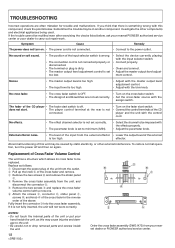
... the screws E, connector D, slider panel C, screws B, and knob A of the cross fader in another component. B E E NOTES: • Do not touch the internal parts of the CD player • The fader start switch is set to minimum (MIN). • Select the channel to be rectified even after exercising the... player and the unit with this unit may lie in the reverse order of this component, check the points below , ask your nearest PIONEER authorized service center or your hand inside the unit. 18 Order the cross fader assembly (DWG1473) from the external effector • Lower...
... the screws E, connector D, slider panel C, screws B, and knob A of the cross fader in another component. B E E NOTES: • Do not touch the internal parts of the CD player • The fader start switch is set to minimum (MIN). • Select the channel to be rectified even after exercising the... player and the unit with this unit may lie in the reverse order of this component, check the points below , ask your nearest PIONEER authorized service center or your hand inside the unit. 18 Order the cross fader assembly (DWG1473) from the external effector • Lower...

