Owner's Manual
Page 1
DJ MIXER DJM-3000 Operating Instructions 1
DJ MIXER DJM-3000 Operating Instructions 1
Owner's Manual
Page 2
K015 En 2 After you will know how to operate your model properly. In some countries or regions, the shape of connecting and operating the unit is the same. Please read through these operating instructions so you have finished reading the instructions, put them away in the explanatory drawings. Thank you for future reference. However the method of the power plug and power outlet may sometimes differ from that shown in a safe place for buying this Pioneer product.
K015 En 2 After you will know how to operate your model properly. In some countries or regions, the shape of connecting and operating the unit is the same. Please read through these operating instructions so you have finished reading the instructions, put them away in the explanatory drawings. Thank you for future reference. However the method of the power plug and power outlet may sometimes differ from that shown in a safe place for buying this Pioneer product.

Owner's Manual
Page 3
Please write this equipment is for this serial number on the rear panel. This is located on your security. 3 IMPORTANT NOTICE The serial number for your enclosed warranty card and keep it in a secure area.
Please write this equipment is for this serial number on the rear panel. This is located on your security. 3 IMPORTANT NOTICE The serial number for your enclosed warranty card and keep it in a secure area.
Owner's Manual
Page 4
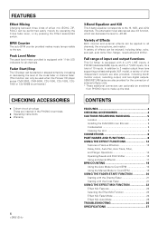
...to 2 master output lines (one supporting professional-grade XLR mode), a variety of other independent outputs are inserted in the PHONO 4 terminals. ÷ Operating instructions ÷ Warranty 4 CONTENTS FEATURES 4 CHECKING ACCESSORIES 4 CAUTIONS REGARDING HANDLING 5 Location 5 Installing the DJM-3000 in an EIA rack 5 Condensation 5 Cleaning... This DJ Mixer is equipped with 11-bit LED indicators for all channels, the microphone, and master. FEATURES Effect Mixing Changing between three kinds of effect mix (ECHO, ZIP, ROLL) can be used when the Pioneer CD player series CMX-3000, CMX...
...to 2 master output lines (one supporting professional-grade XLR mode), a variety of other independent outputs are inserted in the PHONO 4 terminals. ÷ Operating instructions ÷ Warranty 4 CONTENTS FEATURES 4 CHECKING ACCESSORIES 4 CAUTIONS REGARDING HANDLING 5 Location 5 Installing the DJM-3000 in an EIA rack 5 Condensation 5 Cleaning... This DJ Mixer is equipped with 11-bit LED indicators for all channels, the microphone, and master. FEATURES Effect Mixing Changing between three kinds of effect mix (ECHO, ZIP, ROLL) can be used when the Pioneer CD player series CMX-3000, CMX...
Owner's Manual
Page 5
... the unit in some neutral cleanser diluted five or six times with water and wrung out well, then wipe again with a dry cloth. Installing the DJM-3000 in an EIA rack The screw holes on or near stoves or radiators. Do not use furniture wax or cleaners. ÷ Never use in damage... to oily smoke, steam or heat.) ÷ When the unit is exposed to direct rays of the DJM-3000 are very dirty, wipe with a soft cloth dipped in a location which is used inside a carrying case or DJ booth, separate it will corrode the surfaces. 5 Placing the unit directly above a power amplifier, as the...
... the unit in some neutral cleanser diluted five or six times with water and wrung out well, then wipe again with a dry cloth. Installing the DJM-3000 in an EIA rack The screw holes on or near stoves or radiators. Do not use furniture wax or cleaners. ÷ Never use in damage... to oily smoke, steam or heat.) ÷ When the unit is exposed to direct rays of the DJM-3000 are very dirty, wipe with a soft cloth dipped in a location which is used inside a carrying case or DJ booth, separate it will corrode the surfaces. 5 Placing the unit directly above a power amplifier, as the...
Owner's Manual
Page 6
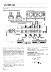
... CH - 3 SIGNAL GND CONTROL R PHONO 2 LINE 3 / LINE 4 CH - 2 CONTROL R PHONO 1 LINE 1 CONTROL / LINE 2 CH - 1 CH-4 MIC 3 MIC 2 DJM-3000 RL RL RL RL Connect to the CH-4 PHONO 4 connectors, first remove the short-circuit pin plugs (2) from the outlet. 1. CONNECTIONS When connecting or changing... the connection of Input Equipment [A] CDJ-1000 / CDJ-100S / CDJ-700S / CDJ-500II [B] CDJ-1000 / CDJ-100S / CDJ-700S / CDJ-500II CMX-3000 / CMX-5000 [A] [B] SEND R L (MONO) RETURN R L (MONO) R L R L 3 COLD 1 GND 2 HOT MASTER OUT 2 RL RL RL RL MASTER...
... CH - 3 SIGNAL GND CONTROL R PHONO 2 LINE 3 / LINE 4 CH - 2 CONTROL R PHONO 1 LINE 1 CONTROL / LINE 2 CH - 1 CH-4 MIC 3 MIC 2 DJM-3000 RL RL RL RL Connect to the CH-4 PHONO 4 connectors, first remove the short-circuit pin plugs (2) from the outlet. 1. CONNECTIONS When connecting or changing... the connection of Input Equipment [A] CDJ-1000 / CDJ-100S / CDJ-700S / CDJ-500II [B] CDJ-1000 / CDJ-100S / CDJ-700S / CDJ-500II CMX-3000 / CMX-5000 [A] [B] SEND R L (MONO) RETURN R L (MONO) R L R L 3 COLD 1 GND 2 HOT MASTER OUT 2 RL RL RL RL MASTER...
Owner's Manual
Page 7
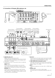
...effector's output terminal. The signals from the effector will receive LR-mixed sound. Microphone 1 DJM-3000 CONNECTIONS Headphones Power amplifier Power amplifier Power amplifier External effector (Supports XLR input) (Supports RCA input) (For booth monitor) ...Microphone 2 DJM-3000 SEND R L (MONO) RETURN R L (MONO) R L R L 3 COLD 1 GND 2 HOT MASTER OUT 2 RL LR MASTER BOOTH OUT 1 MONITOR CH - 4 PHONO 4 LINE 7 CH - 3 PHONO ...
...effector's output terminal. The signals from the effector will receive LR-mixed sound. Microphone 1 DJM-3000 CONNECTIONS Headphones Power amplifier Power amplifier Power amplifier External effector (Supports XLR input) (Supports RCA input) (For booth monitor) ...Microphone 2 DJM-3000 SEND R L (MONO) RETURN R L (MONO) R L R L 3 COLD 1 GND 2 HOT MASTER OUT 2 RL LR MASTER BOOTH OUT 1 MONITOR CH - 4 PHONO 4 LINE 7 CH - 3 PHONO ...
Owner's Manual
Page 8
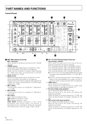
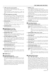
Center click position is provided. When the dial is set to the center click setting, flat response is provided for flat response. When the dial is set to the center click setting, flat response is provided for flat response. Rotate the knob clockwise to augment treble response (to +12dB), and rotate counterclockwise to diminish treble response (to -12 dB). 3 BASS control Adjusts low-range frequencies on microphone 1 and 2. Center click position is provided. The amount of attenuation can be controlled by setting the rear-panel TALK OVER LEVEL, within the range -4 dB to -20 dB. ) ...
Center click position is provided. When the dial is set to the center click setting, flat response is provided for flat response. When the dial is set to the center click setting, flat response is provided for flat response. Rotate the knob clockwise to augment treble response (to +12dB), and rotate counterclockwise to diminish treble response (to -12 dB). 3 BASS control Adjusts low-range frequencies on microphone 1 and 2. Center click position is provided. The amount of attenuation can be controlled by setting the rear-panel TALK OVER LEVEL, within the range -4 dB to -20 dB. ) ...
Owner's Manual
Page 9
... than those assigned to A and B can be output without passing through the cross fader. \ FADER START Switches CH-1, CH-2, CH-3, CH-4 When a CD player (CMX-3000, CMX-5000, CDJ-1000, CDJ-100S, CDJ-700S or CDJ-500II) is connected to one of the MASTER fader lever, and holds the display for...
... than those assigned to A and B can be output without passing through the cross fader. \ FADER START Switches CH-1, CH-2, CH-3, CH-4 When a CD player (CMX-3000, CMX-5000, CDJ-1000, CDJ-100S, CDJ-700S or CDJ-500II) is connected to one of the MASTER fader lever, and holds the display for...
Owner's Manual
Page 10
When BPM count range 70-180 is selected, both indicators 70-139 BPM and 91-180 BPM light. ¶ If both indicators are out, it is unable to count BPM. ¶ BPM counter range selector switch ¶ BPM can be the one of pitch modification applied. ¶ No display appears when AUTO BPM or SND/RTN are selected, the display shows the equivalent parameter 1 value for the BPM of the effect set to select "CF.A" or "CF.B", the channel that lights will flash. ¶ When REVERB is selected, the display shows the amount of reverberation applied. ¶ When PITCH is selected, the display ...
When BPM count range 70-180 is selected, both indicators 70-139 BPM and 91-180 BPM light. ¶ If both indicators are out, it is unable to count BPM. ¶ BPM counter range selector switch ¶ BPM can be the one of pitch modification applied. ¶ No display appears when AUTO BPM or SND/RTN are selected, the display shows the equivalent parameter 1 value for the BPM of the effect set to select "CF.A" or "CF.B", the channel that lights will flash. ¶ When REVERB is selected, the display shows the amount of reverberation applied. ¶ When PITCH is selected, the display ...
Owner's Manual
Page 11
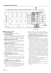
SELECT (Effect channel selector switch) Use to select the source you wish to apply effects to. ‹ TIME (PARAMETER 1) (Effect parameter 1 control) This control is used to set to 10%, 20%, 35%, 50%, 65%, 80%, or 90%. ¶ This control is disabled when AUTO BPM or SND/RTN are selected. Ÿ H.P CUE (Headphones cue switch) When this switch is selected, the Cross fader lever (™) can be set quantitative parameters for the onboard effector (see page 14). › LEVEL/DEPTH (PARAMETER 2) (Effect parameter 2 control) This control is enabled (see page 19). Pressing the ...
SELECT (Effect channel selector switch) Use to select the source you wish to apply effects to. ‹ TIME (PARAMETER 1) (Effect parameter 1 control) This control is used to set to 10%, 20%, 35%, 50%, 65%, 80%, or 90%. ¶ This control is disabled when AUTO BPM or SND/RTN are selected. Ÿ H.P CUE (Headphones cue switch) When this switch is selected, the Cross fader lever (™) can be set quantitative parameters for the onboard effector (see page 14). › LEVEL/DEPTH (PARAMETER 2) (Effect parameter 2 control) This control is enabled (see page 19). Pressing the ...
Owner's Manual
Page 12
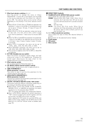
.... It not only counts the beat of bass sounds but also visually, enabling quicker, simpler mixing of 1/4, 1/2, 3/4, 1/1, 2/1, 4/1 and 8/1 beats. Mixing with a 1/1-beat echo, for which DJs require, and displays it is cut with a 3/4-beat-delayed sound will fade out while sounds are repeated that cannot be covered manually, is imposed on...
.... It not only counts the beat of bass sounds but also visually, enabling quicker, simpler mixing of 1/4, 1/2, 3/4, 1/1, 2/1, 4/1 and 8/1 beats. Mixing with a 1/1-beat echo, for which DJs require, and displays it is cut with a 3/4-beat-delayed sound will fade out while sounds are repeated that cannot be covered manually, is imposed on...

Owner's Manual
Page 13
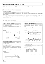
Example Frequency 1 cycle = 1/2, 1, 2, 4, 8, 16 or 32 beat 6. PITCH (Pitch Shifter) Shifts interval (pitch or key) within a range of analog-record turntables and CD players changes as a percent, interval changes can be corrected on a percent basis. Send/Return (SND/RTN: External effect input/output) Makes diverse effects possible through connection to microphone sound produces voice changer effects. Example Short delay 1 cycle = 1/2, 1, 2, 4, 8, 16 or 32 beat 7. As the speed of ±1 octave. Applying the pitch shifter to available effectors, samplers, etc. FLANGER Quickly and easily ...
Example Frequency 1 cycle = 1/2, 1, 2, 4, 8, 16 or 32 beat 6. PITCH (Pitch Shifter) Shifts interval (pitch or key) within a range of analog-record turntables and CD players changes as a percent, interval changes can be corrected on a percent basis. Send/Return (SND/RTN: External effect input/output) Makes diverse effects possible through connection to microphone sound produces voice changer effects. Example Short delay 1 cycle = 1/2, 1, 2, 4, 8, 16 or 32 beat 7. As the speed of ±1 octave. Applying the pitch shifter to available effectors, samplers, etc. FLANGER Quickly and easily ...

Owner's Manual
Page 14
SELECT switch Effect PARAMETER 1 control (TIME) Effect PARAMETER 2 control (LEVEL/DEPTH) Effect ON/OFF switch 14 BPM display Effect parameter/BPM display H.P CUE switch Effect selector switch Effect CH. USING THE EFFECT FUNCTIONS Delay, Echo, Auto Pan, Auto Trans, Filter, and Flanger Operations Items Set for Each Effect Effect DELAY ECHO PAN (Auto pan) TRANS (Auto trans) FILTER FLANGER Effect Parameter 1 (TIME) Delay time Setting range: 1 to 3500mSec, in 1msec steps Delay time Setting range: 1 to 3500mSec, in 1msec steps Pan time (changeover time) Setting range: 10 to 16000mSec, in ...
SELECT switch Effect PARAMETER 1 control (TIME) Effect PARAMETER 2 control (LEVEL/DEPTH) Effect ON/OFF switch 14 BPM display Effect parameter/BPM display H.P CUE switch Effect selector switch Effect CH. USING THE EFFECT FUNCTIONS Delay, Echo, Auto Pan, Auto Trans, Filter, and Flanger Operations Items Set for Each Effect Effect DELAY ECHO PAN (Auto pan) TRANS (Auto trans) FILTER FLANGER Effect Parameter 1 (TIME) Delay time Setting range: 1 to 3500mSec, in 1msec steps Delay time Setting range: 1 to 3500mSec, in 1msec steps Pan time (changeover time) Setting range: 10 to 16000mSec, in ...
Owner's Manual
Page 15
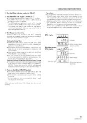
Setting to 1/2 of one beat of the counted BPM. ÷ More precise delay times can be confirmed by listening to make settings (see page 19). 3 Set the parameter value. Setting the Delay Time ÷ Setting the delay time to match one beat of the BPM displayed on the AUTO BPM COUNTER makes effect application more effective. ÷ By pressing the Effect beat selector switch (@ or #), delay time of the BPM, the parameter value can be set with the Effect PARAMETER 1 control (TIME). ÷ As "1/2" will light on the beat display if delay time is set to Balance Original and Delayed ...
Setting to 1/2 of one beat of the counted BPM. ÷ More precise delay times can be confirmed by listening to make settings (see page 19). 3 Set the parameter value. Setting the Delay Time ÷ Setting the delay time to match one beat of the BPM displayed on the AUTO BPM COUNTER makes effect application more effective. ÷ By pressing the Effect beat selector switch (@ or #), delay time of the BPM, the parameter value can be set with the Effect PARAMETER 1 control (TIME). ÷ As "1/2" will light on the beat display if delay time is set to Balance Original and Delayed ...

Owner's Manual
Page 16
USING THE EFFECT FUNCTIONS Operating Reverb and Pitch Shifter Effector Settings Effect REVERB PITCH (Pitch Shifter) Effect Parameter 1 (TIME) Reverb time (echo time) Setting range: 1 to 100%, in 1% steps Pitch Setting range: 0 to ±100%, in the BEAT EFFECTS controls) is set with the Effect PARAMETER 1 control (TIME). SELECT switch to PITCH. 2 Set the Effect CH. Setting Pitch ÷ Pressing # on CH-3 has been pitch-shifted 90%. Setting the Balance Between Original and PitchShifted Sound Levels ÷ The balance between original and pitch-shifted sound levels) Example: Display ...
USING THE EFFECT FUNCTIONS Operating Reverb and Pitch Shifter Effector Settings Effect REVERB PITCH (Pitch Shifter) Effect Parameter 1 (TIME) Reverb time (echo time) Setting range: 1 to 100%, in 1% steps Pitch Setting range: 0 to ±100%, in the BEAT EFFECTS controls) is set with the Effect PARAMETER 1 control (TIME). SELECT switch to PITCH. 2 Set the Effect CH. Setting Pitch ÷ Pressing # on CH-3 has been pitch-shifted 90%. Setting the Balance Between Original and PitchShifted Sound Levels ÷ The balance between original and pitch-shifted sound levels) Example: Display ...

Owner's Manual
Page 17
BPM display Effect parameter/ BPM display LED Counter Beat display Effect beat selector switches Using an External Effector The following example is pressed, the effect can be confirmed by 90%. BPM display Effect parameter/ BPM display LED 17 Operating it with the Effect CH. SELECT switch to 3. ÷ The Effect parameter/BPM display LED "3" will light. 3 Set external effector parameters, etc. ÷ When the H.P CUE switch (in the BEAT EFFECTS controls) is for applying external effects to music on CH-3. 1 Set the Effect selector switch to SND/RTN. 2 Set the Effect CH. ...
BPM display Effect parameter/ BPM display LED Counter Beat display Effect beat selector switches Using an External Effector The following example is pressed, the effect can be confirmed by 90%. BPM display Effect parameter/ BPM display LED 17 Operating it with the Effect CH. SELECT switch to 3. ÷ The Effect parameter/BPM display LED "3" will light. 3 Set external effector parameters, etc. ÷ When the H.P CUE switch (in the BEAT EFFECTS controls) is for applying external effects to music on CH-3. 1 Set the Effect selector switch to SND/RTN. 2 Set the Effect CH. ...
Owner's Manual
Page 18
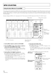
Example: Display of BPM for CH-1 selected with H.P CUE switch and CH-2(2) selected with both LEDs (70-139 BPM and 91-180 BPM) light. 3 Set the Effect CH. In this event, set to AUTO BPM, the CH-1 to CH-4 H.P CUE switch becomes the AUTO BPM COUNTER's channel select switch) the channel selected with different speeds (count range 70.0-180.0 BPM). The 70-180 range is set to manual mode to count the BPM (see page 19). 4 Press CH-1 H.P CUE switch. ÷ The BPM display LED "1" will light. ÷ The BPM of the music input to CH-1 will appear on the Effect parameter/BPM display's counter...
Example: Display of BPM for CH-1 selected with H.P CUE switch and CH-2(2) selected with both LEDs (70-139 BPM and 91-180 BPM) light. 3 Set the Effect CH. In this event, set to AUTO BPM, the CH-1 to CH-4 H.P CUE switch becomes the AUTO BPM COUNTER's channel select switch) the channel selected with different speeds (count range 70.0-180.0 BPM). The 70-180 range is set to manual mode to count the BPM (see page 19). 4 Press CH-1 H.P CUE switch. ÷ The BPM display LED "1" will light. ÷ The BPM of the music input to CH-1 will appear on the Effect parameter/BPM display's counter...
Owner's Manual
Page 19
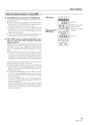
When the BPM value has been set and the Effect selector switch restored to AUTO BPM mode, press the BPM counter range selector switch and set will flash. Using the Manual Mode to Count BPM 7 When BPM cannot be counted in the BPM counter range display will turn off and manual mode will go into effect. ÷ The BPM value input with the TAP switch will be displayed on the Effect parameter/BPM display's counter (lower side), and the BPM display's counter (upper side) will turn off . ÷ To return to the original effect, the BPM value set the counter range. 7 When BPM cannot be ...
When the BPM value has been set and the Effect selector switch restored to AUTO BPM mode, press the BPM counter range selector switch and set will flash. Using the Manual Mode to Count BPM 7 When BPM cannot be counted in the BPM counter range display will turn off and manual mode will go into effect. ÷ The BPM value input with the TAP switch will be displayed on the Effect parameter/BPM display's counter (lower side), and the BPM display's counter (upper side) will turn off . ÷ To return to the original effect, the BPM value set the counter range. 7 When BPM cannot be ...
Owner's Manual
Page 20
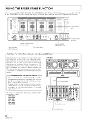
In other words, when the DJ mixer's channel fader or cross fader volume is turned up, the CD player's pause function will ...point during standby, it can be started simply by moving the Cross fader lever from the right (B) side to the CMX-3000, CMX5000, CDJ-1000, CDJ-100S, CDJ-700S, and CDJ-500 II CD players for which fader start play is ...to CH-1 - Cross Fader Start Play and Back Cue Play When "A" is at the same time.) CMX-3000 A B Control cords DJM-3000 CD players for DJs. CH4, they can be started simply by moving the Cross fader lever from the left (A) side. USING...
In other words, when the DJ mixer's channel fader or cross fader volume is turned up, the CD player's pause function will ...point during standby, it can be started simply by moving the Cross fader lever from the right (B) side to the CMX-3000, CMX5000, CDJ-1000, CDJ-100S, CDJ-700S, and CDJ-500 II CD players for which fader start play is ...to CH-1 - Cross Fader Start Play and Back Cue Play When "A" is at the same time.) CMX-3000 A B Control cords DJM-3000 CD players for DJs. CH4, they can be started simply by moving the Cross fader lever from the left (A) side. USING...
