
User Manual
Page 3
English Contents 1 Important 4 Safety 4 For indoor use 4 For outdoor use 4 Notice for USA 4 Notice for Canada 5 Recycling 5 2 Your SDV8625T/27 5 What's in your box 6 3 Get started 7 Installation 7 Connect to the TV 10 Set up a digital tuner with this antenna 10 4 Frequently asked questions 11 5 Warranty and service 11 6 Glossary 12 EN 3
English Contents 1 Important 4 Safety 4 For indoor use 4 For outdoor use 4 Notice for USA 4 Notice for Canada 5 Recycling 5 2 Your SDV8625T/27 5 What's in your box 6 3 Get started 7 Installation 7 Connect to the TV 10 Set up a digital tuner with this antenna 10 4 Frequently asked questions 11 5 Warranty and service 11 6 Glossary 12 EN 3

User Manual
Page 4
... lines, call for qualified emergency help immediately. Even the slightest touch of any of the following measures: • Relocate the receiving antenna. • Increase the separation between equipment and receiver. 4 EN However, there is encouraged to try to a power line can ...Do not install your safety, assume that all loads (weight of the antenna, weight of ice, weight of electrical current. 1 Important Safety This manual contains important information about the Philips indoor/outdoor television antenna. Remember: electric power lines and phone lines look alike. For outdoor ...
... lines, call for qualified emergency help immediately. Even the slightest touch of any of the following measures: • Relocate the receiving antenna. • Increase the separation between equipment and receiver. 4 EN However, there is encouraged to try to a power line can ...Do not install your safety, assume that all loads (weight of the antenna, weight of ice, weight of electrical current. 1 Important Safety This manual contains important information about the Philips indoor/outdoor television antenna. Remember: electric power lines and phone lines look alike. For outdoor ...

User Manual
Page 6
What's in your box 1 2 3 4 1x 1x 1x 1x 5 6 7 8 2x 2x 4x 4x 9 10 11 12 13 1x 1x 4x 1x 14 1x a SDV8625T/27 antenna b Power supply 100-240V AC / 6V DC 500mA c Wall/Mast bracket d Nut e U-Bolts f Mast clamps g Nuts with lock washers 6 EN h 25mm wood screws i 6m coax cable with connectors j Weather boot k Power injector l Plastic anchors m Washer n 40mm Hexagon screw
What's in your box 1 2 3 4 1x 1x 1x 1x 5 6 7 8 2x 2x 4x 4x 9 10 11 12 13 1x 1x 4x 1x 14 1x a SDV8625T/27 antenna b Power supply 100-240V AC / 6V DC 500mA c Wall/Mast bracket d Nut e U-Bolts f Mast clamps g Nuts with lock washers 6 EN h 25mm wood screws i 6m coax cable with connectors j Weather boot k Power injector l Plastic anchors m Washer n 40mm Hexagon screw

User Manual
Page 7
... •• Complete all assembly work on the ground before installing on a wall or an antenna mast. 1 Use the nut , washer , and hexagon screw to attach the antenna to avoid interference. d a Antenna with built-in amplifier b Power inserter module c Splitters or matching transformers (not included) d ...TV or video device 2 Use the screw holes of this antenna system that the power inserter be connected between the antenna and any devices such as a guide to mark position for proper operation of the wall/mast bracket as ...
... •• Complete all assembly work on the ground before installing on a wall or an antenna mast. 1 Use the nut , washer , and hexagon screw to attach the antenna to avoid interference. d a Antenna with built-in amplifier b Power inserter module c Splitters or matching transformers (not included) d ...TV or video device 2 Use the screw holes of this antenna system that the power inserter be connected between the antenna and any devices such as a guide to mark position for proper operation of the wall/mast bracket as ...

User Manual
Page 8
... the concrete wall firmly. 2 Insert U-bolts into the holes. Slide the mast clamps onto the U-bolts . Use wood screws to fix the antenna to the wall/mast bracket. 3.2mm (1/8") 27±5mm 1.1"±0.2" For concrete wall Drill four holes on the ground. Attach the four nuts with lock washers to the wood... on concrete wall, put four plastic anchors into the holes of the wall/mast bracket . 3 For wood wall Use the wood screws to fix the antenna to the U-bolts . 7.9mm (5/16") 35±5mm 1.4"±0.2" 8 EN
... the concrete wall firmly. 2 Insert U-bolts into the holes. Slide the mast clamps onto the U-bolts . Use wood screws to fix the antenna to the wall/mast bracket. 3.2mm (1/8") 27±5mm 1.1"±0.2" For concrete wall Drill four holes on the ground. Attach the four nuts with lock washers to the wood... on concrete wall, put four plastic anchors into the holes of the wall/mast bracket . 3 For wood wall Use the wood screws to fix the antenna to the U-bolts . 7.9mm (5/16") 35±5mm 1.4"±0.2" 8 EN
User Manual
Page 9
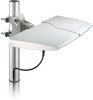
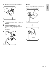
Position the weather boot over the connection. English 3 Attach the assembly to the F connector on the underside of the unit. EN 9 Rotate You can make a 90 degree rotation to the antenna or the mounting post. 4 Rotate the mast in its mount to adjust the direction. 5 Attach the coaxial cable to the mast firmly.
Position the weather boot over the connection. English 3 Attach the assembly to the F connector on the underside of the unit. EN 9 Rotate You can make a 90 degree rotation to the antenna or the mounting post. 4 Rotate the mast in its mount to adjust the direction. 5 Attach the coaxial cable to the mast firmly.

User Manual
Page 10
...8226;• As previously noted, the amplifier (Power injector + Power supply) must be memorized in the tuner automatically . • Connect the antenna directly to the power injector , and then plug the power supply adaptor into a 100-240V AC receptacle. 10 EN Set up properly before you install...8226;• The power injector and power supply are two ways to connect the antenna to the TV: • Connect the antenna to the digital tuner. Tune to the analogue channels and find the best antenna location. Ensure the signal strength is good enough before the tuner can install ...
...8226;• As previously noted, the amplifier (Power injector + Power supply) must be memorized in the tuner automatically . • Connect the antenna directly to the power injector , and then plug the power supply adaptor into a 100-240V AC receptacle. 10 EN Set up properly before you install...8226;• The power injector and power supply are two ways to connect the antenna to the TV: • Connect the antenna to the digital tuner. Tune to the analogue channels and find the best antenna location. Ensure the signal strength is good enough before the tuner can install ...

User Manual
Page 11
... sole option, replacement of purchase. Plug your cable/adapter into the antenna and then into your problem to:accessor ysuppor t@philips.com Limited One-Year Warranty Philips warrants that this product shall be set up a digital tuner with this antenna"). Where should I set up with a digital tuner (see the ... please call 1-919-573-7854.THERE ARE NO OTHER EXPRESS OR IMPLIED WARRANTIES.The liability of Philips is a DC power socket located at : www.philips.com/welcome EN 11 Yes, this antenna is not transferable.To exercise your rights under normal use, in the form of an original ...
... sole option, replacement of purchase. Plug your cable/adapter into the antenna and then into your problem to:accessor ysuppor t@philips.com Limited One-Year Warranty Philips warrants that this product shall be set up a digital tuner with this antenna"). Where should I set up with a digital tuner (see the ... please call 1-919-573-7854.THERE ARE NO OTHER EXPRESS OR IMPLIED WARRANTIES.The liability of Philips is a DC power socket located at : www.philips.com/welcome EN 11 Yes, this antenna is not transferable.To exercise your rights under normal use, in the form of an original ...

User Manual
Page 12
... today digital television (DTV) signals are also supported, so that up to six standard-definition "virtual channels" can be broadcast on a single 6 MHz TV channel. Antenna A device, such as a rod or wire, which lies between 300 MHz and 3 GHz (3000 MHz). An unbalanced transmission line with multiple stages for digital television...
... today digital television (DTV) signals are also supported, so that up to six standard-definition "virtual channels" can be broadcast on a single 6 MHz TV channel. Antenna A device, such as a rod or wire, which lies between 300 MHz and 3 GHz (3000 MHz). An unbalanced transmission line with multiple stages for digital television...


