User Manual
Page 5
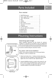
... transmitter location. fig.2 Wall Mount 5 Nuts 2 5. U-Bolts 2 6. Nuts with connectors 1 10. For indoor wall mount installation: NOTE: Do all antenna assembly work on the ground before fig.1 installing on a wall or an antenna mast. 1. If possible locate a stud to 6VDC 1 3. MANT940 Antenna 1 2. Power supply 120V to screw into. Attach main body to allow for the four 2" wood...
... transmitter location. fig.2 Wall Mount 5 Nuts 2 5. U-Bolts 2 6. Nuts with connectors 1 10. For indoor wall mount installation: NOTE: Do all antenna assembly work on the ground before fig.1 installing on a wall or an antenna mast. 1. If possible locate a stud to 6VDC 1 3. MANT940 Antenna 1 2. Power supply 120V to screw into. Attach main body to allow for the four 2" wood...
User Manual
Page 7
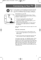
... the Power Supply DC plug to the Power Injector then plug the power supply adapter into a 110/120 Volt AC receptacle. The power injector and power supply is to replace the cable with either RG-6 or RG-6 Quad Shield cable. Safety Note - A note about coaxial cable - Connect the coaxial cable from an ANTENNA instead of RG-59 coaxial cable. MANT940...
... the Power Supply DC plug to the Power Injector then plug the power supply adapter into a 110/120 Volt AC receptacle. The power injector and power supply is to replace the cable with either RG-6 or RG-6 Quad Shield cable. Safety Note - A note about coaxial cable - Connect the coaxial cable from an ANTENNA instead of RG-59 coaxial cable. MANT940...

