User Manual
Page 3
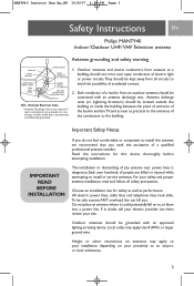
... of entrance of accidental contact. IMPORTANT READ BEFORE INSTALLATION The installation or dismantling of a qualified professional antenna installer. National Electrical Code * Antenna Discharge Unit is not required if lead in and the TV, and as near power lines is permanently... an outdoor antenna should be safe, assume ANY overhead line can kill you seek the assistance of any antenna near as performance. NEC - MANT940 Instruct Eng Sp_SM 10/8/07 4:38 PM Page 3 Safety Instructions EN Philips MANT940 Indoor /Outdoor UHF/ VHF Television antenna Antenna grounding and ...
... of entrance of accidental contact. IMPORTANT READ BEFORE INSTALLATION The installation or dismantling of a qualified professional antenna installer. National Electrical Code * Antenna Discharge Unit is not required if lead in and the TV, and as near power lines is permanently... an outdoor antenna should be safe, assume ANY overhead line can kill you seek the assistance of any antenna near as performance. NEC - MANT940 Instruct Eng Sp_SM 10/8/07 4:38 PM Page 3 Safety Instructions EN Philips MANT940 Indoor /Outdoor UHF/ VHF Television antenna Antenna grounding and ...
User Manual
Page 4
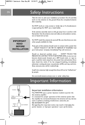
...devices such as splitters, matching transformers, networks, etc. Be sure that they will remove it fall , get away from the power lines and antenna. Once clear, check the victim. Have someone else call for medical help . Do all excellent conductors of this important notice may result in... power injection module to fall . MANT940 Instruct Eng Sp_SM 10/8/07 4:38 PM Page 4 EN Safety Instructions Take the time to plan your local power company immediately.They will not be connected between the antenna and any part of the antenna should come in damaging the power injector...
...devices such as splitters, matching transformers, networks, etc. Be sure that they will remove it fall , get away from the power lines and antenna. Once clear, check the victim. Have someone else call for medical help . Do all excellent conductors of this important notice may result in... power injection module to fall . MANT940 Instruct Eng Sp_SM 10/8/07 4:38 PM Page 4 EN Safety Instructions Take the time to plan your local power company immediately.They will not be connected between the antenna and any part of the antenna should come in damaging the power injector...
User Manual
Page 5
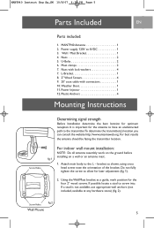
... Installation determine the best location for the four 2" wood screws. For indoor wall mount installation: NOTE: Do all antenna assembly work on the ground before fig.1 installing on a wall or an antenna mast. 1. If a stud is important for later adjustment (fig. ...1). 2. It is not available, use appropriate wall anchors (not included, available at any hardware store) (fig. 2). MANT940 Instruct Eng Sp_SM 10/8/07 4:38 PM Page 5 Parts Included EN Parts included: 1. MANT940 Antenna 1 2. Nuts 2 5. U-Bolts 2 6. L-Bracket 1 8. 2" Wood Screws 4 9. 20' coax cable with lock ...
... Installation determine the best location for the four 2" wood screws. For indoor wall mount installation: NOTE: Do all antenna assembly work on the ground before fig.1 installing on a wall or an antenna mast. 1. If a stud is important for later adjustment (fig. ...1). 2. It is not available, use appropriate wall anchors (not included, available at any hardware store) (fig. 2). MANT940 Instruct Eng Sp_SM 10/8/07 4:38 PM Page 5 Parts Included EN Parts included: 1. MANT940 Antenna 1 2. Nuts 2 5. U-Bolts 2 6. L-Bracket 1 8. 2" Wood Screws 4 9. 20' coax cable with lock ...
User Manual
Page 6
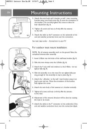
... fully, just snug enough for later adjustment (fig. 3). 4. fig.5 7. Attach the main body of the bracket. Insert U-Bolts into the holes of the antenna direction will be done by rotating the mast in place (fig. 5). 5. See next steps under - Adjustment of the wall/mast bracket (fig. 4). 2. ... mast bracket using cross head screw (fig. 3) note the orientation of the unit and weather protection boot over the connection (fig.6). MANT940 Instruct Eng Sp_SM 10/8/07 4:38 PM Page 6 EN Mounting Instructions 3. Fully tighten this screw to allow for the assembly to the U-Bolts -
... fully, just snug enough for later adjustment (fig. 3). 4. fig.5 7. Attach the main body of the bracket. Insert U-Bolts into the holes of the antenna direction will be done by rotating the mast in place (fig. 5). 5. See next steps under - Adjustment of the wall/mast bracket (fig. 4). 2. ... mast bracket using cross head screw (fig. 3) note the orientation of the unit and weather protection boot over the connection (fig.6). MANT940 Instruct Eng Sp_SM 10/8/07 4:38 PM Page 6 EN Mounting Instructions 3. Fully tighten this screw to allow for the assembly to the U-Bolts -
User Manual
Page 7
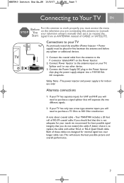
...coaxial cable. Connections to your television owner's manual) then set it to receive the signal from the antenna to the F connector labeled ANT on the television you are designed for indoor use only! MANT940 Instruct Eng Sp_SM 10/8/07 4:38 PM Page 7 Connecting to Your TV EN STOP Before You ...Start For this antenna to work properly, you must be placed in-line between the antenna and before any other device. 3. Connect the...
...coaxial cable. Connections to your television owner's manual) then set it to receive the signal from the antenna to the F connector labeled ANT on the television you are designed for indoor use only! MANT940 Instruct Eng Sp_SM 10/8/07 4:38 PM Page 7 Connecting to Your TV EN STOP Before You ...Start For this antenna to work properly, you must be placed in-line between the antenna and before any other device. 3. Connect the...


