
User Manual
Page 4
... CONTACT WITH THE POWER LINE, or you too can become electrocuted. Use 8 AWG or larger ground wire. Raise the completed antenna after assembly. Call your installation procedure. If he has stopped breathing, immediately administer cardiopulmonary resuscitation (CPR) and stay with a power line . . .... EN Safety Instructions IMPORTANT READ BEFORE INSTALLATION lighting arresting device. Height or other people available for medical help . If the antenna assembly starts to an airport, or local ordinances. Do NOT install the antenna by people. Be sure that they will remove it fall...
... CONTACT WITH THE POWER LINE, or you too can become electrocuted. Use 8 AWG or larger ground wire. Raise the completed antenna after assembly. Call your installation procedure. If he has stopped breathing, immediately administer cardiopulmonary resuscitation (CPR) and stay with a power line . . .... EN Safety Instructions IMPORTANT READ BEFORE INSTALLATION lighting arresting device. Height or other people available for medical help . If the antenna assembly starts to an airport, or local ordinances. Do NOT install the antenna by people. Be sure that they will remove it fall...

User Manual
Page 5
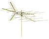
Screws (1-3/4 5 r. Cross Piece (for U-Bolt Assembly) 3 z. UHF Boom-B 2 c. Tubing Brace 2 .j Phasing Wire 2 k. End Caps 8 q. Wing-Nuts 1 7 v. UHF Boom-A 2 carefully to antenna ...t. U-Bolt 3 y. Antenna Saddle .......... 1 *Quantities listed include those which may be attached to determine your antenna, additional hardware may already be required. Before starting assembly, please Parts included: read through the instructions a. Nuts 6 w. Included with EN Note: For final installation and connection of your b. VHF Boom-A 1 d. Reflector ...
Screws (1-3/4 5 r. Cross Piece (for U-Bolt Assembly) 3 z. UHF Boom-B 2 c. Tubing Brace 2 .j Phasing Wire 2 k. End Caps 8 q. Wing-Nuts 1 7 v. UHF Boom-A 2 carefully to antenna ...t. U-Bolt 3 y. Antenna Saddle .......... 1 *Quantities listed include those which may be attached to determine your antenna, additional hardware may already be required. Before starting assembly, please Parts included: read through the instructions a. Nuts 6 w. Included with EN Note: For final installation and connection of your b. VHF Boom-A 1 d. Reflector ...

User Manual
Page 6
... VHF Portion • Rotate reflector element rods on VHF Boom-A and VHF Boom-B into place. Don't apply 6 excess pressure to assembled UHF Boom (previous step) using two 1-1/2˝ screws and wing-nuts. Don't apply excess pressure to reflector element rods. • Insert ...; screw and lock washer. • Attach Reflector Arm Mounting Brackets to reflector element rods. To fully secure Reflector Arms, snap into place. Assembly of UHF Portion • Rotate reflector element rods into locking tabs and tighten screws. NOTE: When rotating element rods, grasp close to pivot and...
... VHF Portion • Rotate reflector element rods on VHF Boom-A and VHF Boom-B into place. Don't apply 6 excess pressure to assembled UHF Boom (previous step) using two 1-1/2˝ screws and wing-nuts. Don't apply excess pressure to reflector element rods. • Insert ...; screw and lock washer. • Attach Reflector Arm Mounting Brackets to reflector element rods. To fully secure Reflector Arms, snap into place. Assembly of UHF Portion • Rotate reflector element rods into locking tabs and tighten screws. NOTE: When rotating element rods, grasp close to pivot and...

User Manual
Page 7
Assembly EN • Attach one 46˝ Element to hole A in wire to UHF antenna using 1-1/2˝ screw and lock washers. Repeat each steps with 1-1/2˝ ... Boom-B into VHF Boom-A and secure using 3/4˝ screws, washers, and wing-nuts. • Insert end caps at ends of all booms. Mast Assembly (Mast not included) • Assemble U-bolts to cross pieces. • Use saddle on center of VHF Boom. Secure with second boom for 2nd boom as well. • Attach...
Assembly EN • Attach one 46˝ Element to hole A in wire to UHF antenna using 1-1/2˝ screw and lock washers. Repeat each steps with 1-1/2˝ ... Boom-B into VHF Boom-A and secure using 3/4˝ screws, washers, and wing-nuts. • Insert end caps at ends of all booms. Mast Assembly (Mast not included) • Assemble U-bolts to cross pieces. • Use saddle on center of VHF Boom. Secure with second boom for 2nd boom as well. • Attach...

User Manual
Page 8
...mast standoff to mast. • Insert wire in standoff and tighten with pliers. • Power lines should be as far away as possible. • Assemble U-bolts in wall mounts with lock washers and nuts. • Secure mounts to house with screw-type standoffs. • Tighten standoffs with... assembled antenna through U-bolts. • Tighten U-bolts securely. All U-bolts should be on TV set. • Attach antenna lead-in wire. • Form drip ...
...mast standoff to mast. • Insert wire in standoff and tighten with pliers. • Power lines should be as far away as possible. • Assemble U-bolts in wall mounts with lock washers and nuts. • Secure mounts to house with screw-type standoffs. • Tighten standoffs with... assembled antenna through U-bolts. • Tighten U-bolts securely. All U-bolts should be on TV set. • Attach antenna lead-in wire. • Form drip ...

User Manual
Page 9
... the product, and is only required for older TV sets with the dated proof of purchase, must be free from defects in material, workmanship and assembly, under normal use, in accordance with the specifications and warnings, for repair or replacement. For most newer sets, simply connect cable from state to state...
... the product, and is only required for older TV sets with the dated proof of purchase, must be free from defects in material, workmanship and assembly, under normal use, in accordance with the specifications and warnings, for repair or replacement. For most newer sets, simply connect cable from state to state...