

Owner's Manual
Page 2
I Fold this page out Index Bobbin Bobbin case Bobbin thread Buttonholing Carrying case Carrying handle Cleaning Electrical connection Finger-tip stitch Finger-tip stitch Finger-tip stitch Finger-tip stitch Foot control buttons, buttons, buttons, buttons, Models 1014 Model 1019 Model 1035 Model 1037 and 1015 Light bulb Machine feed Needle Needle position Oiling Presser bar lifter Reverse sewing Sewing feet Sewing mechanism Slot-threading Special accessories Special sewing feet Spool of thread Stitch length Stitch program chart Straight-stitch needle Stretch stitches ...
I Fold this page out Index Bobbin Bobbin case Bobbin thread Buttonholing Carrying case Carrying handle Cleaning Electrical connection Finger-tip stitch Finger-tip stitch Finger-tip stitch Finger-tip stitch Foot control buttons, buttons, buttons, buttons, Models 1014 Model 1019 Model 1035 Model 1037 and 1015 Light bulb Machine feed Needle Needle position Oiling Presser bar lifter Reverse sewing Sewing feet Sewing mechanism Slot-threading Special accessories Special sewing feet Spool of thread Stitch length Stitch program chart Straight-stitch needle Stretch stitches ...

Owner's Manual
Page 4
Make sure you pull out the power cord plug whenever you want to change needle, sewing foot, bobbin or needle plate, when you clean and oil the machine, or when you have to interrupt sewing and leave the machine for United Kingdom only The wires in this appliance may not correspond with the letter N or coloured black. Please note: When a 13-ampere plug is used a 3-ampere fuse has to be connected to the terminal which is coloured blue must be fitted. I Parts of this mains lead are coloured in accordance with the following code: Blue: Neutral Brown: Live As the colours of the wires in ...
Make sure you pull out the power cord plug whenever you want to change needle, sewing foot, bobbin or needle plate, when you clean and oil the machine, or when you have to interrupt sewing and leave the machine for United Kingdom only The wires in this appliance may not correspond with the letter N or coloured black. Please note: When a 13-ampere plug is used a 3-ampere fuse has to be connected to the terminal which is coloured blue must be fitted. I Parts of this mains lead are coloured in accordance with the following code: Blue: Neutral Brown: Live As the colours of the wires in ...

Owner's Manual
Page 5
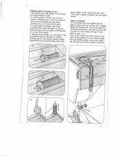
work support (1015-1037) detachable Reach under the detachable with your left hand (N), swing the left (0), and lift it out toward Then open its The accessory box sewing feet, thread is used to arrow. the the carrying rear, as case cover, fold indicated by an the Then lift the cover off handle to and other put away accessories. N i N Model 1014 on a sewing reason, this has two holes at sewing cabinet (not ill.) be placed on Model 1014 can cabinet. Removing the carrying case cover To lift off . lid (Q). For this machine the back. ) 1 Removing and opening ...
work support (1015-1037) detachable Reach under the detachable with your left hand (N), swing the left (0), and lift it out toward Then open its The accessory box sewing feet, thread is used to arrow. the the carrying rear, as case cover, fold indicated by an the Then lift the cover off handle to and other put away accessories. N i N Model 1014 on a sewing reason, this has two holes at sewing cabinet (not ill.) be placed on Model 1014 can cabinet. Removing the carrying case cover To lift off . lid (Q). For this machine the back. ) 1 Removing and opening ...

Owner's Manual
Page 7
Electrical connection sspTPewluawuiksgtihcenhPgtp.h1lieun0gt4fo.o0otYht ieoncutowronamttlrhloaelocuhomtiulnaetect.ohfiiPsntrehneeosswsomcmrakeceaahtsditynaenerf.dor scWhoonhwternonlyiinosutphpleauctieltlduhseitnrmatthiaoecnhmi(nNae)c.haiwnaey,agthaien foot as Foot control dsPPterlapaercsrtseessstdseheowedwi,nfnotgoht.hteeTcfhoapnesettdremoarllo,truheanendtdhmeerathctpheheeidnmatelaabcrilshueni.nse. Electronic foot control aPthSolaolwlisfdrai.eteyidTosuRnhcreeeotnfautihlntleheepd=ti,oeeprlrhceeaiscgnlptfagrerotdehnpdleioecwstosoffeoprotohftosepfsceeotmwhendeaitnrcognhleinsespeederlteveodei....
Electrical connection sspTPewluawuiksgtihcenhPgtp.h1lieun0gt4fo.o0otYht ieoncutowronamttlrhloaelocuhomtiulnaetect.ohfiiPsntrehneeosswsomcmrakeceaahtsditynaenerf.dor scWhoonhwternonlyiinosutphpleauctieltlduhseitnrmatthiaoecnhmi(nNae)c.haiwnaey,agthaien foot as Foot control dsPPterlapaercsrtseessstdseheowedwi,nfnotgoht.hteeTcfhoapnesettdremoarllo,truheanendtdhmeerathctpheheeidnmatelaabcrilshueni.nse. Electronic foot control aPthSolaolwlisfdrai.eteyidTosuRnhcreeeotnfautihlntleheepd=ti,oeeprlrhceeaiscgnlptfagrerotdehnpdleioecwstosoffeoprotohftosepfsceeotmwhendeaitnrcognhleinsespeederlteveodei....
Owner's Manual
Page 8
cut for end tmNhreedSaimudmalolnustonproetohelelsinsogpfodtohilsrcep.aindP:uasunhsdetphslemacasepllooolr of unreeling O Large disc 0 in spools of front of thread at the right. onto the spool Upper threading tottRFahafkoaekgeries-us-teupuihdpoprteeholalele0edvav)sie,nneerdrgwfr,1moidn1mbru3gao.swttbfhoebolittoeht.wieniPntnouintlehltseoeldtoihrslteelo"Nttuahnp(Prt"deoaapttndhhodeesfirtolieomfnt . iFrTnioghtorhetnttwhthdeorr-aesnwlaeodet idttglobueaitdshceekewQliiennftgoto,nosfdltohrgateuwPindoeeanen0dedletaihnnrhtdeooaltddthheeer. 4 on pin Load thread reel with diagonal of ...
cut for end tmNhreedSaimudmalolnustonproetohelelsinsogpfodtohilsrcep.aindP:uasunhsdetphslemacasepllooolr of unreeling O Large disc 0 in spools of front of thread at the right. onto the spool Upper threading tottRFahafkoaekgeries-us-teupuihdpoprteeholalele0edvav)sie,nneerdrgwfr,1moidn1mbru3gao.swttbfhoebolittoeht.wieniPntnouintlehltseoeldtoihrslteelo"Nttuahnp(Prt"deoaapttndhhodeesfirtolieomfnt . iFrTnioghtorhetnttwhthdeorr-aesnwlaeodet idttglobueaitdshceekewQliiennftgoto,nosfdltohrgateuwPindoeeanen0dedletaihnnrhtdeooaltddthheeer. 4 on pin Load thread reel with diagonal of ...

Owner's Manual
Page 9
Hold the hand wheel steady and turn the stop motion knob toward you start winding the bobbin, disen gage the sewing mechanism. Disengaging the sewing mechanism Before you . One of the guide. Threading the needle Thread the needle from you. 5 I other into the right thread guide, the other to back. After bobbin winding, tighten the knob again by turning it away from front to the righE of the threads is then pulled into the left thread guide on the needle holder.
Hold the hand wheel steady and turn the stop motion knob toward you start winding the bobbin, disen gage the sewing mechanism. Disengaging the sewing mechanism Before you . One of the guide. Threading the needle Thread the needle from you. 5 I other into the right thread guide, the other to back. After bobbin winding, tighten the knob again by turning it away from front to the righE of the threads is then pulled into the left thread guide on the needle holder.

Owner's Manual
Page 10
Pull the thread from the spool and draw it out. RI__II... Push the bobbin toward the bobbin win der and wind a few turns of thread on spindle 101 so that pin 0 enters slot N. Push the full bobbin toward the left and take it through guide P and around thread retainer stud 114. LI_.._1 __.J Winding Disengage the sewing mechanism (page 5). Fit a second spool holder to the machine and place a spool of thread on the bobbin. Place a bobbin on it. Then pull the thread toward the right, press down the foot control pedal and wind the bobbin. The bobbin winder stops auto ...
Pull the thread from the spool and draw it out. RI__II... Push the bobbin toward the bobbin win der and wind a few turns of thread on spindle 101 so that pin 0 enters slot N. Push the full bobbin toward the left and take it through guide P and around thread retainer stud 114. LI_.._1 __.J Winding Disengage the sewing mechanism (page 5). Fit a second spool holder to the machine and place a spool of thread on the bobbin. Place a bobbin on it. Then pull the thread toward the right, press down the foot control pedal and wind the bobbin. The bobbin winder stops auto ...

Owner's Manual
Page 11
Removing bobbin case and bobbin Remove cover 108 or open free arm cover 122. Then draw the thread into slot 0 and under the spring into the bobbin case so that the thread unreels toward the back (N). The bobbin cannot fall out as long as you keep latch N pulled out. Inserting the bobbin Insert the filled bobbin into eye P. 7 Pull out latch N, then lift out the bobbin case, release the latch and take out the bobbin.
Removing bobbin case and bobbin Remove cover 108 or open free arm cover 122. Then draw the thread into slot 0 and under the spring into the bobbin case so that the thread unreels toward the back (N). The bobbin cannot fall out as long as you keep latch N pulled out. Inserting the bobbin Insert the filled bobbin into eye P. 7 Pull out latch N, then lift out the bobbin case, release the latch and take out the bobbin.

Owner's Manual
Page 12
Replace cover 108 or close free arm cover 122. Turn hand wheel 102 toward the left and back under the sewing foot. 8 Pull the bobbin thread out of the needle hole and lay both threads toward you until the needle moves down and up again and the take-up lever is up latch P and push the bobbin case onto stud 0 as far as it will go. Inserting the bobbin case Pull up . Drawing up the bobbin thread Hold the needle thread a little taut. Stud 0 and latch P must point upwards. Release the latch. Cutout N must be flush.
Replace cover 108 or close free arm cover 122. Turn hand wheel 102 toward the left and back under the sewing foot. 8 Pull the bobbin thread out of the needle hole and lay both threads toward you until the needle moves down and up again and the take-up lever is up latch P and push the bobbin case onto stud 0 as far as it will go. Inserting the bobbin case Pull up . Drawing up the bobbin thread Hold the needle thread a little taut. Stud 0 and latch P must point upwards. Release the latch. Cutout N must be flush.

Owner's Manual
Page 13
foot is raised. (Before you the take-up foot is lowered for Thread cutter dimsaTnoetthawwotechinhtnehtwighnearbeefracodactuodsokttwt.tecooarPufructdsttlulhelotterhtthteihpaseenrbaemdwansc.ospkreouk.rblllDobitquarhuatre.wemoRfstlhatohietseeltohtcrheaeatedds 9 Presser bar lifter Lever 115 has four positions: N o The sewing remove the toward you work, turn the hand wheel to raise the needle and lever.) = sesLDiTlannoohamsttwe.reenerreistsrnietngitnwmghoiepetnecogxphpstirurtfeRaiosos-hotsnathetiirfitcsotkhbbrreaaadmcriabksarleotindsfetittlrenoiigfrgamutlahrsfntl....
foot is raised. (Before you the take-up foot is lowered for Thread cutter dimsaTnoetthawwotechinhtnehtwighnearbeefracodactuodsokttwt.tecooarPufructdsttlulhelotterhtthteihpaseenrbaemdwansc.ospkreouk.rblllDobitquarhuatre.wemoRfstlhatohietseeltohtcrheaeatedds 9 Presser bar lifter Lever 115 has four positions: N o The sewing remove the toward you work, turn the hand wheel to raise the needle and lever.) = sesLDiTlannoohamsttwe.reenerreistsrnietngitnwmghoiepetnecogxphpstirurtfeRaiosos-hotsnathetiirfitcsotkhbbrreaaadmcriabksarleotindsfetittlrenoiigfrgamutlahrsfntl....

Owner's Manual
Page 14
P = Both tensions are correct. It must not slide down freely by its own weight, but should be adjusted. 4 j - 4 I 10 Lower tension O = Regulating screw. R = Lower tension too loose or upper tension too tight. The higher the number, the tighter the tension. Q-' -'I . The normal tension setting is in the white range between 3 and 5. Q = Upper tension too loose or lower tension too tight. Turn it left for a looser tension, or right for a tighter tension. The correct lower tension Let the bobbin case with a full bobbin hang down by the thread. Once the lower tension has ...
P = Both tensions are correct. It must not slide down freely by its own weight, but should be adjusted. 4 j - 4 I 10 Lower tension O = Regulating screw. R = Lower tension too loose or upper tension too tight. The higher the number, the tighter the tension. Q-' -'I . The normal tension setting is in the white range between 3 and 5. Q = Upper tension too loose or lower tension too tight. Turn it left for a looser tension, or right for a tighter tension. The correct lower tension Let the bobbin case with a full bobbin hang down by the thread. Once the lower tension has ...

Owner's Manual
Page 15
jegulating the stitch length he numbers on stitch length control 106 dicate the stitch length in millimeters On todets 1014 and 1015 the stitch length jes from 0 to 4 mm, on Models 1019 to 7 from 0 to 6 mm. , the control so that the number indicat the stitch lenght chosen is opposite k N. . 0 shows how to set the stitch length trol for sewing stretch stitches (red stitch ibols on push buttons). As tong as you keep this button depressed, the machine sews backwards. 11 Reverse sewing Press button 119.
jegulating the stitch length he numbers on stitch length control 106 dicate the stitch length in millimeters On todets 1014 and 1015 the stitch length jes from 0 to 4 mm, on Models 1019 to 7 from 0 to 6 mm. , the control so that the number indicat the stitch lenght chosen is opposite k N. . 0 shows how to set the stitch length trol for sewing stretch stitches (red stitch ibols on push buttons). As tong as you keep this button depressed, the machine sews backwards. 11 Reverse sewing Press button 119.

Owner's Manual
Page 16
Finger-tip 1015 controls on Models 1014 and A, B, C; A B 12 Buttons for buttonholing DtrBheuel2Eet-tallomeasnfsimtntiBgcnzeititergshidzepalalelegpsoupzsspitughistsziecteadihodgnbasut(sitsttecochelne,sap2raaignnmgedmb1fo7ur)t.tsoenttifnogr E Elastic triple zigzag stitch, 3.5-mm zigzag stitch 3.5 mm F Elastic triple zigzag 5-mm zigzag stitch stitch, 5.0 mm G Elastic triple straight stitch Straight stitch -
Finger-tip 1015 controls on Models 1014 and A, B, C; A B 12 Buttons for buttonholing DtrBheuel2Eet-tallomeasnfsimtntiBgcnzeititergshidzepalalelegpsoupzsspitughistsziecteadihodgnbasut(sitsttecochelne,sap2raaignnmgedmb1fo7ur)t.tsoenttifnogr E Elastic triple zigzag stitch, 3.5-mm zigzag stitch 3.5 mm F Elastic triple zigzag 5-mm zigzag stitch stitch, 5.0 mm G Elastic triple straight stitch Straight stitch -

Owner's Manual
Page 17
Buttons for buttonholing Button B is also used as clearing button for releasing the pushed buttons and for setting the left needle position (see page 17). D Elastic triple zigzag stitch, 2 mm 2-mm zigzag stich E Elastic triple zigzag stitch, 3.5 mm 3.5-mm zigzag stitch F Elastic triple zigzag stitch, 5 mm 5-mm zigzag stitch G Elastic triple straight stitch Straight stitch M Honeycomb stitch Elastic stitch 13 Finger-tip controls on Model 1019 A, B, C;
Buttons for buttonholing Button B is also used as clearing button for releasing the pushed buttons and for setting the left needle position (see page 17). D Elastic triple zigzag stitch, 2 mm 2-mm zigzag stich E Elastic triple zigzag stitch, 3.5 mm 3.5-mm zigzag stitch F Elastic triple zigzag stitch, 5 mm 5-mm zigzag stitch G Elastic triple straight stitch Straight stitch M Honeycomb stitch Elastic stitch 13 Finger-tip controls on Model 1019 A, B, C;

Owner's Manual
Page 18
Buttons for buttonholing Button B is also used as clearing button for releasing the pushed buttons and for setting the left needle position (see page 17). D Elastic triple zigzag stitch, 2 mm 2-mm zigzag stitch E Elastic triple zigzag stitch, 3.5 mm 3.5-mm zigzag stitch F Elastic triple zigzag stitch, 5 mm 5-mm zigzag stitch G Elastic triple straight stitch Straight stitch I Closed overlock stitch Joining stitch K Overlock stitch Shell-edge stitch M Honeycomb stitch Elastic stitch 14 Finger-tip controls on Model 1035 A, B, C;
Buttons for buttonholing Button B is also used as clearing button for releasing the pushed buttons and for setting the left needle position (see page 17). D Elastic triple zigzag stitch, 2 mm 2-mm zigzag stitch E Elastic triple zigzag stitch, 3.5 mm 3.5-mm zigzag stitch F Elastic triple zigzag stitch, 5 mm 5-mm zigzag stitch G Elastic triple straight stitch Straight stitch I Closed overlock stitch Joining stitch K Overlock stitch Shell-edge stitch M Honeycomb stitch Elastic stitch 14 Finger-tip controls on Model 1035 A, B, C;

Owner's Manual
Page 19
Buttons for buttonholing Button B is also used as clearing button for releasing the pushed buttons and for setting the left needle position (see page 17). o Elastic triple zigzag stitch, 2 mm 2-mm zigzag stitch E Elastic triple zigzag stitch, 3.5 mm 3.5-mm zigzag stitch F Elastic triple zigzag stitch, 5 mm 5-mm zigzag stitch G Elastic triple straight stitch Straight stitch H Pullover stitch Blindstitch I Closed overlock stitch Joining stitch K Overlock stitch Shell-edge stitch L Feather stitch Elastic decorative stitch M Honeycomb stitch Elastic stitch 4 n \I/I cD 111 II 15 ___ ___...
Buttons for buttonholing Button B is also used as clearing button for releasing the pushed buttons and for setting the left needle position (see page 17). o Elastic triple zigzag stitch, 2 mm 2-mm zigzag stitch E Elastic triple zigzag stitch, 3.5 mm 3.5-mm zigzag stitch F Elastic triple zigzag stitch, 5 mm 5-mm zigzag stitch G Elastic triple straight stitch Straight stitch H Pullover stitch Blindstitch I Closed overlock stitch Joining stitch K Overlock stitch Shell-edge stitch L Feather stitch Elastic decorative stitch M Honeycomb stitch Elastic stitch 4 n \I/I cD 111 II 15 ___ ___...
Owner's Manual
Page 20
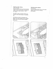
This chart also contains possible applications. All zigzag, utility and stretch stitches are listed in width when button G is pressed too. Selecting utihty stitches (white symbols) Push the desired button and turn length control as far as it will go the stitch (red symbol). 16 All stitches and stitch combinations are halved in the stitch program chart on pages 26-29. Selecting stretch stitches (red symbols) Push the desired button and turn the stitch length control to the number indicating the desired stitch length between 1 and 4 or 1 and 6.
This chart also contains possible applications. All zigzag, utility and stretch stitches are listed in width when button G is pressed too. Selecting utihty stitches (white symbols) Push the desired button and turn length control as far as it will go the stitch (red symbol). 16 All stitches and stitch combinations are halved in the stitch program chart on pages 26-29. Selecting stretch stitches (red symbols) Push the desired button and turn the stitch length control to the number indicating the desired stitch length between 1 and 4 or 1 and 6.

Owner's Manual
Page 21
Utility-and- C?D G 4 C) I . stretch-stitch combinations 1he various stitch combinations are shown jn the chart and at the end of this booklet, ogether with sewing instructions. For xample if you want to sew an elastic lindstitch, push buttons M and F, select a titch length between 1 and 4. Right needle position (on Model 1037): push buttons H and I H Central needle position: push button G. Selecting the needle position for straight stitching Left needle position: push button B.
Utility-and- C?D G 4 C) I . stretch-stitch combinations 1he various stitch combinations are shown jn the chart and at the end of this booklet, ogether with sewing instructions. For xample if you want to sew an elastic lindstitch, push buttons M and F, select a titch length between 1 and 4. Right needle position (on Model 1037): push buttons H and I H Central needle position: push button G. Selecting the needle position for straight stitching Left needle position: push button B.

Owner's Manual
Page 22
Dropping the machine feed Remove cover 108 or free arm cover 122. Replace cover 108 or close free arm cover. 122. Then tighten screw N. Changing the needle Raise the needle bar. Then hold the needle, loosen screw N and pull the needle out downwards. Twin needles with the flat side of 1.4 mm may be used for embroidering, darning, basting etc. For sewing, push the drop-feed control toward N. Open free arm cover 122. Insert a new System 130/705 H needle (with a needle distance of its shank facing toward the back) and push it up as far as it will go. The feed dog is ...
Dropping the machine feed Remove cover 108 or free arm cover 122. Replace cover 108 or close free arm cover. 122. Then tighten screw N. Changing the needle Raise the needle bar. Then hold the needle, loosen screw N and pull the needle out downwards. Twin needles with the flat side of 1.4 mm may be used for embroidering, darning, basting etc. For sewing, push the drop-feed control toward N. Open free arm cover 122. Insert a new System 130/705 H needle (with a needle distance of its shank facing toward the back) and push it up as far as it will go. The feed dog is ...

Owner's Manual
Page 23
attaching Hole R and screw an edge guide and the darning foot. Screw S serves to secure the sewing foot holder on the presser bar. 19 Place the sewing foot under the sewing foot holder and hold it in slot P. When attaching a sewing foot make sure stud 0 enters slot P. Lower presser bar lifter 115 and at the same time reposition the sewing foot so that stud 0 Q are used fits for in place with your left hand. Changing the sewing foot To release the sewing foot push the red button N.
attaching Hole R and screw an edge guide and the darning foot. Screw S serves to secure the sewing foot holder on the presser bar. 19 Place the sewing foot under the sewing foot holder and hold it in slot P. When attaching a sewing foot make sure stud 0 enters slot P. Lower presser bar lifter 115 and at the same time reposition the sewing foot so that stud 0 Q are used fits for in place with your left hand. Changing the sewing foot To release the sewing foot push the red button N.