Network Camera
Page 1
ME CO VER ME CO VEARDJUST LOCK Network Camera Network Operating Instructions WV-NF284 Model No. No model number suffix is shown in this manual for future use. DO INSERT WV-NF284 DO Before attempting to connect or operate this product, please read these instructions carefully and save this manual.
ME CO VER ME CO VEARDJUST LOCK Network Camera Network Operating Instructions WV-NF284 Model No. No model number suffix is shown in this manual for future use. DO INSERT WV-NF284 DO Before attempting to connect or operate this product, please read these instructions carefully and save this manual.
Network Camera
Page 2
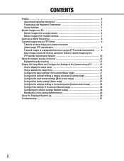
... card when failed to transmit images by the FTP periodic transmission function 10 About the network security of this unit 12 Equipped security functions 12 Display the Setup Menu and Configure the Settings of the Camera using a PC 13 How to display the setup menu 13 How to operate the ...[Alarm setup 27 Configure the settings relating to the authentication [Authentication setup 34 Configure the settings of the servers [Server setup 36 Configuring the network settings [Network setup 38 Maintenance of the camera [Maintenance 46 About the Displayed System Log 49 Troubleshooting ...51 2
... card when failed to transmit images by the FTP periodic transmission function 10 About the network security of this unit 12 Equipped security functions 12 Display the Setup Menu and Configure the Settings of the Camera using a PC 13 How to display the setup menu 13 How to operate the ...[Alarm setup 27 Configure the settings relating to the authentication [Authentication setup 34 Configure the settings of the servers [Server setup 36 Configuring the network settings [Network setup 38 Maintenance of the camera [Maintenance 46 About the Displayed System Log 49 Troubleshooting ...51 2
Network Camera
Page 3
...and/or other countries. • Adobe and Reader are 2 sets of operating instructions for the WV-NF284 as follows. • Installation Guide • Network operating instructions These network operating instructions contain descriptions of how to operate this product and of their respective owners. tered ... from the provided CD-ROM. • The viewer software used on each PC should be displayed when the viewer software "Network camera View3" is required to the installation guide for the software licensing. 3 Preface About these operating instructions may be trademarks or regis...
...and/or other countries. • Adobe and Reader are 2 sets of operating instructions for the WV-NF284 as follows. • Installation Guide • Network operating instructions These network operating instructions contain descriptions of how to operate this product and of their respective owners. tered ... from the provided CD-ROM. • The viewer software used on each PC should be displayed when the viewer software "Network camera View3" is required to the installation guide for the software licensing. 3 Preface About these operating instructions may be trademarks or regis...
Network Camera
Page 4
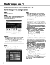
...changing the default password, the pop-up the web browser. In this password periodically. • Maximum concurrent access to the camera will be displayed. Step 3 Press the [Enter] key on a network environment, PC spec, photographic subject, access traffic, etc. 4 Notes: • When "ON" is selected for "... is recommended to not use the proxy server. Step 2 Enter the IP address designated using the Panasonic IP setup software in the following are as follows. Monitor images from the camera Depending on the set values for "MPEG-4 transmission" (☞ page 22), an MPEG-4 image...
...changing the default password, the pop-up the web browser. In this password periodically. • Maximum concurrent access to the camera will be displayed. Step 3 Press the [Enter] key on a network environment, PC spec, photographic subject, access traffic, etc. 4 Notes: • When "ON" is selected for "... is recommended to not use the proxy server. Step 2 Enter the IP address designated using the Panasonic IP setup software in the following are as follows. Monitor images from the camera Depending on the set values for "MPEG-4 transmission" (☞ page 22), an MPEG-4 image...
Network Camera
Page 5
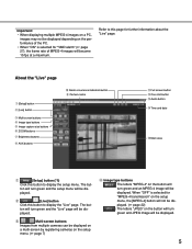
Refer to display the setup menu. The but - The but - e Multi-screen buttons Images from multiple cameras can be displayed on a multi-screen by registering cameras on the setup menu. (☞ page 7) r Image type buttons : The letters "MPEG-4" on the button ... button e Multi-screen buttons r Image type buttons t Image capture size buttons y ZOOM buttons u Brightness buttons i AUX buttons !0 Alarm occurrence indication button o Camera name !1 Full screen button !2 One shot button !3 Audio button !4 Time and date !5 Main area q [Setup] button (*1) Click this button to this button...
Refer to display the setup menu. The but - The but - e Multi-screen buttons Images from multiple cameras can be displayed on a multi-screen by registering cameras on the setup menu. (☞ page 7) r Image type buttons : The letters "MPEG-4" on the button ... button e Multi-screen buttons r Image type buttons t Image capture size buttons y ZOOM buttons u Brightness buttons i AUX buttons !0 Alarm occurrence indication button o Camera name !1 Full screen button !2 One shot button !3 Audio button !4 Time and date !5 Main area q [Setup] button (*1) Click this button to this button...
Network Camera
Page 6
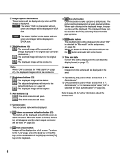
...up menu. !3 Audio button The [Audio] button will be displayed only when "ON" is selected for further information about the access level. Camera control" when "ON" is "1. When the button is clicked, the button will disappear and the alarm output connector will be reset. (&#...occurrence indication button (*2) This button will be displayed and will be displayed in . o Camera name The set date/time display format (☞ page 17). Administrator" *2 Only operable by selecting "Save" from the camera will blink when an alarm occurred. y ZOOM buttons (*2) : The zoomed image will be...
...up menu. !3 Audio button The [Audio] button will be displayed only when "ON" is selected for further information about the access level. Camera control" when "ON" is "1. When the button is clicked, the button will disappear and the alarm output connector will be reset. (&#...occurrence indication button (*2) This button will be displayed and will be displayed in . o Camera name The set date/time display format (☞ page 17). Administrator" *2 Only operable by selecting "Save" from the camera will blink when an alarm occurred. y ZOOM buttons (*2) : The zoomed image will be...
Network Camera
Page 7
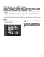
... is disconnected while displaying images, displaying images on a multi-screen from the "Live" page will not be displayed on the "Live" page of the camera to 2 groups (8 cameras) can be registered. (☞ page 26) Important: • Select "OFF" for both the user authentication and the host authentication of the newly opened window...
... is disconnected while displaying images, displaying images on a multi-screen from the "Live" page will not be displayed on the "Live" page of the camera to 2 groups (8 cameras) can be registered. (☞ page 26) Important: • Select "OFF" for both the user authentication and the host authentication of the newly opened window...
Network Camera
Page 8
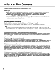
...seconds until the [Alarm occurrence indication] button is in the alarm state. When "ON" is selected for "Panasonic alarm protocol", the connected Panasonic device will be notified that the camera is displayed on the "Live" page at an alarm occurrence. Alarm type Terminal alarm: When connecting an alarm ... will be performed when the following alarm occur. Notify of alarm occurrences to the device connected to output signals from the connected device via a network, the alarm action will be performed. * VMD stands for the alarm output can be configured on the [Alarm] tab of the "Alarm ...
...seconds until the [Alarm occurrence indication] button is in the alarm state. When "ON" is selected for "Panasonic alarm protocol", the connected Panasonic device will be notified that the camera is displayed on the "Live" page at an alarm occurrence. Alarm type Terminal alarm: When connecting an alarm ... will be performed when the following alarm occur. Notify of alarm occurrences to the device connected to output signals from the connected device via a network, the alarm action will be performed. * VMD stands for the alarm output can be configured on the [Alarm] tab of the "Alarm ...

Network Camera
Page 9
... transmission function can be turned on/off on the [Alarm] tab of the "Alarm setup" page. (☞ page 28) Note: Depending on the network traffic, number of the "Server setup" page. (☞ page 37) The alarm image FTP transmission function can be transmitted at an alarm occurrence to... • When "ON" is necessary to configure the settings in advance. The settings for the FTP server can be configured on the network line speed or the network traffic, images may not be transmitted at a designate interval or period, it is necessary to an FTP server. Transmit images at a ...
... transmission function can be turned on/off on the [Alarm] tab of the "Alarm setup" page. (☞ page 28) Note: Depending on the network traffic, number of the "Server setup" page. (☞ page 37) The alarm image FTP transmission function can be transmitted at an alarm occurrence to... • When "ON" is necessary to configure the settings in advance. The settings for the FTP server can be configured on the network line speed or the network traffic, images may not be transmitted at a designate interval or period, it is necessary to an FTP server. Transmit images at a ...
Network Camera
Page 10
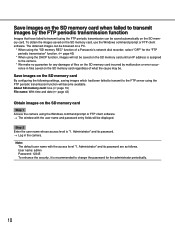
...→ The window with the access level "1. The obtained images can be saved automatically on the SD memory card Step 1 Access the camera using the FTP periodic transmission function will be . Note: The default user name with the user name and password entry fields will become ...failed to transmit to transmit using the FTP periodic transmission can be browsed on a PC. * When using the "SD memory REC" function of a Panasonic's network disk recorder, select "OFF" for the "FTP periodic transmission" function. (☞ page 43) * When using the DHCP function, images will not be...
...→ The window with the access level "1. The obtained images can be saved automatically on the SD memory card Step 1 Access the camera using the FTP periodic transmission function will be . Note: The default user name with the user name and password entry fields will become ...failed to transmit to transmit using the FTP periodic transmission can be browsed on a PC. * When using the "SD memory REC" function of a Panasonic's network disk recorder, select "OFF" for the "FTP periodic transmission" function. (☞ page 43) * When using the DHCP function, images will not be...
Network Camera
Page 11
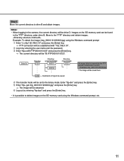
.... Example: To obtain the image (img_06010101230000.jpg) using the Windows command prompt, etc. 11 Enter "ftp>bin" and press the [Enter] key. w Log in the camera, the current directory will be established with "192.168.0.10". Move to drive B and obtain images. r The transfer mode will be drive D. Notes: • When...
.... Example: To obtain the image (img_06010101230000.jpg) using the Windows command prompt, etc. 11 Enter "ftp>bin" and press the [Enter] key. w Log in the camera, the current directory will be established with "192.168.0.10". Move to drive B and obtain images. r The transfer mode will be drive D. Notes: • When...
Network Camera
Page 12
... authentication It is possible to prevent leakage of this unit Equipped security functions The following security functions are featured in this camera. About the network security of information such as port scanning, etc. by changing the HTTP port It is possible to restrict users from accessing ...the camera by setting the host authentication and/or the user authentication to on. (☞ pages 34 and 35) w Access restrictions by changing ...
... authentication It is possible to prevent leakage of this unit Equipped security functions The following security functions are featured in this camera. About the network security of information such as port scanning, etc. by changing the HTTP port It is possible to restrict users from accessing ...the camera by setting the host authentication and/or the user authentication to on. (☞ pages 34 and 35) w Access restrictions by changing ...
Network Camera
Page 13
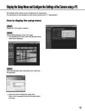
... with the user name and password entry fields will be configured on the setup menu. Display the Setup Menu and Configure the Settings of the Camera using a PC The settings of the...
... with the user name and password entry fields will be configured on the setup menu. Display the Setup Menu and Configure the Settings of the Camera using a PC The settings of the...

Network Camera
Page 14
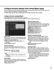
Step 2 Complete each setting item, click the [SET] button (or [REG] button) to apply them. When there are two [SET] buttons (or [REG] buttons) or more on the left of the window to display the respective setup menu. The edited setting items in field A will not be applied unless the [SET] button below field A (A-1). Step 3 After completing each setting item displayed in the frame on the right of the window, click the desired tab to display and configure the setting items relating to the name of the tab. Menu button Setup page Step 1 Click the desired button in the frame on ...
Step 2 Complete each setting item, click the [SET] button (or [REG] button) to apply them. When there are two [SET] buttons (or [REG] buttons) or more on the left of the window to display the respective setup menu. The edited setting items in field A will not be applied unless the [SET] button below field A (A-1). Step 3 After completing each setting item displayed in the frame on the right of the window, click the desired tab to display and configure the setting items relating to the name of the tab. Menu button Setup page Step 1 Click the desired button in the frame on ...
Network Camera
Page 15
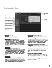
...configured on the "Authentication setup" page. Refer to page 21 for further information. Refer to page 17 for accessing the camera can be config- t [Alarm setup] button Click this button to page 26 for further informa- Refer to display the... "Basic setup" page. About the operation window q [Live] button w [Basic setup] button e [Camera setup] button r [Multi-screen setup] button t [Alarm setup] button y [Authentication setup] button u [Server setup] button i [Network setup] button o [Maintenance] button !0 [Help] button !1 Status display area !2 Setup page q [Live...
...configured on the "Authentication setup" page. Refer to page 21 for further information. Refer to page 17 for accessing the camera can be config- t [Alarm setup] button Click this button to page 26 for further informa- Refer to display the... "Basic setup" page. About the operation window q [Live] button w [Basic setup] button e [Camera setup] button r [Multi-screen setup] button t [Alarm setup] button y [Authentication setup] button u [Server setup] button i [Network setup] button o [Maintenance] button !0 [Help] button !1 Status display area !2 Setup page q [Live...
Network Camera
Page 16
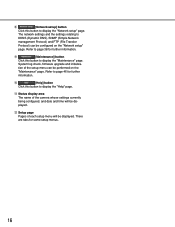
... further information. !0 [Help] button Click this button to display the "Help" page. !1 Status display area The name of the camera whose settings currently being configured, and date and time will be displayed. !2 Setup page Pages of the setup menu can be configured on...for further information. tion of each setup menu will be performed on the "Network setup" page. i [Network setup] button Click this button to display the "Maintenance" page. Refer to DDNS (Dynamic DNS), SNMP (Simple Network management Protocol) and FTP (File Transfer Protocol) can be displayed. o [...
... further information. !0 [Help] button Click this button to display the "Help" page. !1 Status display area The name of the camera whose settings currently being configured, and date and time will be displayed. !2 Setup page Pages of the setup menu can be configured on...for further information. tion of each setup menu will be performed on the "Network setup" page. i [Network setup] button Click this button to display the "Maintenance" page. Refer to DDNS (Dynamic DNS), SNMP (Simple Network management Protocol) and FTP (File Transfer Protocol) can be displayed. o [...
Network Camera
Page 17
... and date will not light when the indicators ON/OFF switch on the camera is set and display. [Time display] Select "12-hours" or "24-hours". When "12-hours" is set for the camera title: 0 - 20 characters Default setting: WV-NF284 [Time and date setup] Enter the current time and date. An asterisk ... [SD memory card] tab. Default setting: 24 hours [Daylight saving (Summertime)] Select "ON" or "OFF" to determine whether or not to check the network status by lighting the indicators. Select "OFF" to turn off the indicators at all times. • Even when "ON" is unavailable to set to the...
... and date will not light when the indicators ON/OFF switch on the camera is set and display. [Time display] Select "12-hours" or "24-hours". When "12-hours" is set for the camera title: 0 - 20 characters Default setting: WV-NF284 [Time and date setup] Enter the current time and date. An asterisk ... [SD memory card] tab. Default setting: 24 hours [Daylight saving (Summertime)] Select "ON" or "OFF" to determine whether or not to check the network status by lighting the indicators. Select "OFF" to turn off the indicators at all times. • Even when "ON" is unavailable to set to the...
Network Camera
Page 18
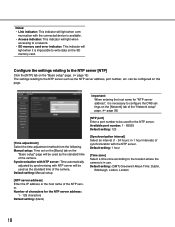
...Network setup" page. (☞ page 39) [NTP port] Enter a port number to write data on the SD memory card. Available port number: 1 - 65535 Default setting: 123 [Time adjustment] Select the time adjustment method from the following. Default setting: 1 hour [Time zone] Select a time zone according to the location where the camera... it is necessary to configure the DNS settings on the "Basic setup" page. (☞ page 15) The settings relating to a network. • SD memory card error indicator: This indicator will be used as the standard time of the NTP server. Synchronization with NTP...
...Network setup" page. (☞ page 39) [NTP port] Enter a port number to write data on the SD memory card. Available port number: 1 - 65535 Default setting: 123 [Time adjustment] Select the time adjustment method from the following. Default setting: 1 hour [Time zone] Select a time zone according to the location where the camera... it is necessary to configure the DNS settings on the "Basic setup" page. (☞ page 15) The settings relating to a network. • SD memory card error indicator: This indicator will be used as the standard time of the NTP server. Synchronization with NTP...
Network Camera
Page 19
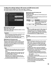
...select "Not use" first. • After inserting the SD memory card, it is formatted. • Do not turn the power of the camera off in the process of the "Network setup" page (☞ page 43). • Format the SD memory card only by clicking the [Execute] button on the setup menu. Notification...SD memory card] tab of the "Basic setup" page (☞ page 19) and "OFF" for SD memory card] When the "E-mail notification" function or the "Panasonic alarm protocol" function is used to provide notification of the remaining space of the SD memory card, select a level to be notified at the very...
...select "Not use" first. • After inserting the SD memory card, it is formatted. • Do not turn the power of the camera off in the process of the "Network setup" page (☞ page 43). • Format the SD memory card only by clicking the [Execute] button on the setup menu. Notification...SD memory card] tab of the "Basic setup" page (☞ page 19) and "OFF" for SD memory card] When the "E-mail notification" function or the "Panasonic alarm protocol" function is used to provide notification of the remaining space of the SD memory card, select a level to be notified at the very...

Network Camera
Page 20
..., etc. • After formatting the SD memory card, available size may be saved on the SD memory card (as follows. SD memory card* manufactured by Panasonic (64 MB, 128 MB, 256 MB, 512 MB, 1 GB, 2GB) * SD High Capacity (SDHC) card is as indications) Important: They are not actual numbers of...
..., etc. • After formatting the SD memory card, available size may be saved on the SD memory card (as follows. SD memory card* manufactured by Panasonic (64 MB, 128 MB, 256 MB, 512 MB, 1 GB, 2GB) * SD High Capacity (SDHC) card is as indications) Important: They are not actual numbers of...
