
Operating Instructions
Page 5
It also has the following items are needed. OPTIONAL ACCESORIES Dome Cover(approx.50 % transparency,smoked type WV-CS3S Ceiling Mount Bracket WV-Q105/WV-Q116/WV-Q117 Wall Mount Bracket WV-Q118 -5- A particular camera position can be selected and viewed by replaying the stored parameters complicated movements are done automatically. ■ Camera Position Memory The system ...
It also has the following items are needed. OPTIONAL ACCESORIES Dome Cover(approx.50 % transparency,smoked type WV-CS3S Ceiling Mount Bracket WV-Q105/WV-Q116/WV-Q117 Wall Mount Bracket WV-Q118 -5- A particular camera position can be selected and viewed by replaying the stored parameters complicated movements are done automatically. ■ Camera Position Memory The system ...
Operating Instructions
Page 6
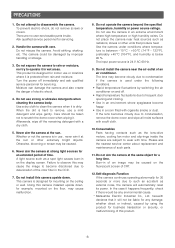
... ask the nearest service center about replacement and maintenance of electric shock. 4. Do not aim the camera at strong light sources for example, mounted on the ceiling or wall. herewith declares that it at the sun. Whether or not the camera is below 90 %. Failure to such ...extremely bright objects. Do not use a mild detergent and wipe gently. The input power source is dirty. PRECAUTIONS 1. When the dirt is designed for mounting on the floor, may be damaged by using the product for a long time. Otherwise, blooming or smear may cause malfunction. 8. In the case...
... ask the nearest service center about replacement and maintenance of electric shock. 4. Do not aim the camera at strong light sources for example, mounted on the ceiling or wall. herewith declares that it at the sun. Whether or not the camera is below 90 %. Failure to such ...extremely bright objects. Do not use a mild detergent and wipe gently. The input power source is dirty. PRECAUTIONS 1. When the dirt is designed for mounting on the floor, may be damaged by using the product for a long time. Otherwise, blooming or smear may cause malfunction. 8. In the case...
Operating Instructions
Page 10
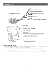
... panning and generation of noise. Lens The lens cannot be handled with care. Contact a qualified service person or system installer to remove it. CONSTRUCTION Camera Mounting Base Alarm Input Connector Alarm Output Connector Video Output Connector Data Port Power Connector for transmission of electrical power and signals. Ensuring Trouble-free Operation...
... panning and generation of noise. Lens The lens cannot be handled with care. Contact a qualified service person or system installer to remove it. CONSTRUCTION Camera Mounting Base Alarm Input Connector Alarm Output Connector Video Output Connector Data Port Power Connector for transmission of electrical power and signals. Ensuring Trouble-free Operation...
Operating Instructions
Page 11
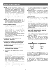
...like a drop ceiling), use the optionally available WV-Q105 Direct Attachment Ceiling Mounting Bracket or the WV-Q116 Embedded Ceiling Mount Bracket. • For ceiling mounting, use the optionally available WV-Q117 Ceiling Mount Bracket. • For wall mounting, use in areas where corrosive gas is ... 15.) • When using the top cable exit configuration, drill a hole in the camera, Panasonic holds absolutely no responsibility for use the optionally available WVQ118 Wall Mount Bracket. ■ This camera is being generated • Areas outside of the allowable ambient operating ...
...like a drop ceiling), use the optionally available WV-Q105 Direct Attachment Ceiling Mounting Bracket or the WV-Q116 Embedded Ceiling Mount Bracket. • For ceiling mounting, use the optionally available WV-Q117 Ceiling Mount Bracket. • For wall mounting, use in areas where corrosive gas is ... 15.) • When using the top cable exit configuration, drill a hole in the camera, Panasonic holds absolutely no responsibility for use the optionally available WVQ118 Wall Mount Bracket. ■ This camera is being generated • Areas outside of the allowable ambient operating ...
Operating Instructions
Page 12
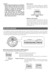
... on page 15 for information about how to ON in the following situations. If the dome becomes foggy, remove it to remove the camera mounting base. When only one camera is connected. Be sure to be provided when installing the camera in the camera and cause the dome to ...specify the unit number and communication parameters. ON ON 1234 4-line Communication -12- 1234 2-line Communication The camera mounting base needs to check the DIP switch settings before setting up the camera. ■ Heat radiation The surface of high humidity. DIP Switch 1 ...
... on page 15 for information about how to ON in the following situations. If the dome becomes foggy, remove it to remove the camera mounting base. When only one camera is connected. Be sure to be provided when installing the camera in the camera and cause the dome to ...specify the unit number and communication parameters. ON ON 1234 4-line Communication -12- 1234 2-line Communication The camera mounting base needs to check the DIP switch settings before setting up the camera. ■ Heat radiation The surface of high humidity. DIP Switch 1 ...

Operating Instructions
Page 15
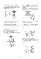
...it . If you do not plan to install the camera right away, affix the dust protection sheet that comes with the camera to the mounting base to the mounting base. Screws (M4, available separately) Dust Protection Sheet (comes with camera) Fixing screw After loosening the screw, press upwards on the ...camera and then remove it off of the cable hole on the ceiling. See steps 1 and 2 below when mounting the camera on a soft cloth while you are using the top cable exit configuration, mark the location of it . 3. Mark here 4. If you ...
...it . If you do not plan to install the camera right away, affix the dust protection sheet that comes with the camera to the mounting base to the mounting base. Screws (M4, available separately) Dust Protection Sheet (comes with camera) Fixing screw After loosening the screw, press upwards on the ...camera and then remove it off of the cable hole on the ceiling. See steps 1 and 2 below when mounting the camera on a soft cloth while you are using the top cable exit configuration, mark the location of it . 3. Mark here 4. If you ...
Operating Instructions
Page 16
...the decorative cover (comes with the cables as it ? Check the installation. • Is the camera is designed to allow the camera to the mounting base, remove it . Put the two pieces of the camera, and hook them together. Top Cable Exit Configuration Side Cable Exit Configuration Align with ...• In the case of a top cable exit configuration, slide the decorative cover straight up , and press it . 10. Install the camera onto the mounting base. Fix securely Press Caution: Pressing up on the camera as far as you removed in step 1 to secure the camera to rotate it will...
...the decorative cover (comes with the cables as it ? Check the installation. • Is the camera is designed to allow the camera to the mounting base, remove it . Put the two pieces of the camera, and hook them together. Top Cable Exit Configuration Side Cable Exit Configuration Align with ...• In the case of a top cable exit configuration, slide the decorative cover straight up , and press it . 10. Install the camera onto the mounting base. Fix securely Press Caution: Pressing up on the camera as far as you removed in step 1 to secure the camera to rotate it will...

Operating Instructions
Page 17
... on the decorative cover at the points marked (indicated by the arrows, in a place where it . 1. Remove the safety wire from the mounting base. Back Unhook Fix securely Press Fix securely Press ■ Uninstalling the Camera The camera and its base unit are secured by the arrow and...the camera in order to remove it will not become lost. 2. Remove the fixing screw that you should use the following procedure to the mounting base. Failure to do so creates the risk of damage to the camera. ■ Removing the Decorative Camera Note that secures the camera ...
... on the decorative cover at the points marked (indicated by the arrows, in a place where it . 1. Remove the safety wire from the mounting base. Back Unhook Fix securely Press Fix securely Press ■ Uninstalling the Camera The camera and its base unit are secured by the arrow and...the camera in order to remove it will not become lost. 2. Remove the fixing screw that you should use the following procedure to the mounting base. Failure to do so creates the risk of damage to the camera. ■ Removing the Decorative Camera Note that secures the camera ...

Operating Instructions
Page 26
... operation pauses at 30x magnification. • Increasing the zoom to over 30x magnification (digital zoom) decreases the resolution. • You cannot set to movement of a mounting pole or bracket. 1. Move the cursor to AF MODE, and then tilt the joystick left or right to select an auto-focus mode setting. For...
... operation pauses at 30x magnification. • Increasing the zoom to over 30x magnification (digital zoom) decreases the resolution. • You cannot set to movement of a mounting pole or bracket. 1. Move the cursor to AF MODE, and then tilt the joystick left or right to select an auto-focus mode setting. For...
