Operating Instructions
Page 1
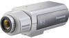
No model number suffix is shown in this manual for future use. Lens: Option Before attempting to connect or operate this product, please read these instructions carefully and save this manual. WV-CP504 This illustration represents WV-CP500. Operating Instructions Color CCTV Camera WV-CP500 Model No.
No model number suffix is shown in this manual for future use. Lens: Option Before attempting to connect or operate this product, please read these instructions carefully and save this manual. WV-CP504 This illustration represents WV-CP500. Operating Instructions Color CCTV Camera WV-CP500 Model No.
Operating Instructions
Page 2
Adobe® Reader® is not installed on the PC, download the latest Adobe® Reader® from the Adobe web site and install it. Trademarks and registered trademarks Adobe and Reader are either registered trademarks or trademarks of 2 sets: these operating instructions (PDF) and Installation Guide. Refer to the installation guide for further information about how to configure the settings of the camera. When the Adobe® Reader® is required to read PDF. Preface About the user manuals The operating instructions of the camera consist of Adobe Systems Incorporated in the ...
Adobe® Reader® is not installed on the PC, download the latest Adobe® Reader® from the Adobe web site and install it. Trademarks and registered trademarks Adobe and Reader are either registered trademarks or trademarks of 2 sets: these operating instructions (PDF) and Installation Guide. Refer to the installation guide for further information about how to configure the settings of the camera. When the Adobe® Reader® is required to read PDF. Preface About the user manuals The operating instructions of the camera consist of Adobe Systems Incorporated in the ...
Operating Instructions
Page 3
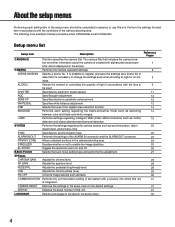
Electronic sensitivity enhancement setting [SENS UP 12 6. Digital noise reduction function setting [DNR 14 8. Image stabilizer setting [STABILIZER 25 14. Electronic zoom setting [EL-ZOOM 26 Back focus setting [BACK-FOCUS SETUP 27 Special menu setting [SPECIAL SETUP 29 Chroma level adjustment [CHROMA GAIN 29 Aperture level adjustment [AP GAIN 29 Pedestal level adjustment [PEDESTAL 29 Chroma phase (hue) adjustment [HUE 29 Flaw compensation [PIX OFF 30 Communication setting [COMMUNICATION 31 Default resetting [CAMERA RESET 31 Serial number viewing [SER.NO 31 Language ...
Electronic sensitivity enhancement setting [SENS UP 12 6. Digital noise reduction function setting [DNR 14 8. Image stabilizer setting [STABILIZER 25 14. Electronic zoom setting [EL-ZOOM 26 Back focus setting [BACK-FOCUS SETUP 27 Special menu setting [SPECIAL SETUP 29 Chroma level adjustment [CHROMA GAIN 29 Aperture level adjustment [AP GAIN 29 Pedestal level adjustment [PEDESTAL 29 Chroma phase (hue) adjustment [HUE 29 Flaw compensation [PIX OFF 30 Communication setting [COMMUNICATION 31 Default resetting [CAMERA RESET 31 Serial number viewing [SER.NO 31 Language ...
Operating Instructions
Page 4
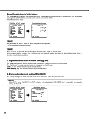
ALC/ELC Selects the method of controlling the quantity of light in accordance with alphanumerics and sym- SHUTTER Specifies the electronic shutter speed. WHITE BAL Specifies white balance adjustment. SYSTEM Performs the settings regarding the camera system such as motion detection and object abandonment/removal detection. STABILIZER Decides whether or not to use this unit. EL-ZOOM Toggles the electronic zoom on the screen. PEDESTAL Adjusts the pedestal (brightness) level. SER.NO. The camera title that it is created with the lens to be used in case that ...
ALC/ELC Selects the method of controlling the quantity of light in accordance with alphanumerics and sym- SHUTTER Specifies the electronic shutter speed. WHITE BAL Specifies white balance adjustment. SYSTEM Performs the settings regarding the camera system such as motion detection and object abandonment/removal detection. STABILIZER Decides whether or not to use this unit. EL-ZOOM Toggles the electronic zoom on the screen. PEDESTAL Adjusts the pedestal (brightness) level. SER.NO. The camera title that it is created with the lens to be used in case that ...
Operating Instructions
Page 5
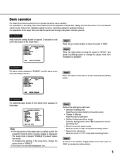
... mode from "DISABLE" to prevent operation errors. Screenshot 1 Hold down button to move the cursor to operate the setup menu basically. MODEL WV-CP500 SERIES CAMERA ID OFF CAMERA SYSTEM BACK-FOCUS SPECIAL LANGUAGE END SETUP ENABLE Step 3 Move the cursor to the item to "TOP" and ..."ENABLE". • The cursor is called up with the operation buttons after calling up the setup menu on the connected video monitor. MODEL WV-CP500 SERIES CAMERA ID OFF CAMERA SYSTEM BACK-FOCUS SPECIAL LANGUAGE END SETUP DISABLE Step 1 Press the up or down the setting button for approx...
... mode from "DISABLE" to prevent operation errors. Screenshot 1 Hold down button to move the cursor to operate the setup menu basically. MODEL WV-CP500 SERIES CAMERA ID OFF CAMERA SYSTEM BACK-FOCUS SPECIAL LANGUAGE END SETUP ENABLE Step 3 Move the cursor to the item to "TOP" and ..."ENABLE". • The cursor is called up with the operation buttons after calling up the setup menu on the connected video monitor. MODEL WV-CP500 SERIES CAMERA ID OFF CAMERA SYSTEM BACK-FOCUS SPECIAL LANGUAGE END SETUP DISABLE Step 1 Press the up or down the setting button for approx...
Operating Instructions
Page 6
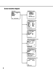
Screen transition diagram Top screen MODEL WV-CP500 SERIES CAMERA ID OFF CAMERA SYSTEM BACK-FOCUS SPECIAL LANGUAGE END SETUP ENABLE 6 "CAMERA ID" screen **CAMERA ID** 0123456789 ABCDEFGHIJKLM NOPQRSTUVWXYZ SPACE POSI RET TOP ...
Screen transition diagram Top screen MODEL WV-CP500 SERIES CAMERA ID OFF CAMERA SYSTEM BACK-FOCUS SPECIAL LANGUAGE END SETUP ENABLE 6 "CAMERA ID" screen **CAMERA ID** 0123456789 ABCDEFGHIJKLM NOPQRSTUVWXYZ SPACE POSI RET TOP ...
Operating Instructions
Page 7
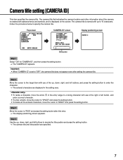
... cursor to specify the camera title. Follow the procedure below to "POSI" and press the setting button after setting the camera title. Top screen MODEL WV-CP500 SERIES CAMERA ID ON CAMERA SYSTEM BACK-FOCUS SPECIAL LANGUAGE END SETUP ENABLE "CAMERA ID" screen **CAMERA ID** 0123456789 ABCDEFGHIJKLM NOPQRSTUVWXYZ SPACE POSI RET TOP...
... cursor to specify the camera title. Follow the procedure below to "POSI" and press the setting button after setting the camera title. Top screen MODEL WV-CP500 SERIES CAMERA ID ON CAMERA SYSTEM BACK-FOCUS SPECIAL LANGUAGE END SETUP ENABLE "CAMERA ID" screen **CAMERA ID** 0123456789 ABCDEFGHIJKLM NOPQRSTUVWXYZ SPACE POSI RET TOP...
Operating Instructions
Page 8
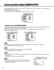
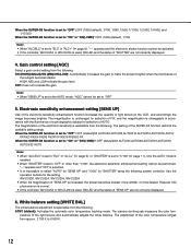
The settings configured on each setting screen inidicates a scene file number. **ALC CONT**(1) BACK LIGHT COMP SUPER-D5 ON Scene file number LEVEL MANUAL ABS ...|... 0 - + RET TOP END 8 Change between day and night, SCENE1 can be configured on the ALARM IN setting or shortcut operation. (+ Pages 23 and 24) "SCENE1" is set as the settings of "SCENE2". Step 4 Edit the settings to be changed and saved as the default setting. Register a scene file [SCENE1/SCENE2] It is selected, configure the settings of "ALC/ELC" through "i-VMD". (☞ Pages 9 - 20) When using ...
The settings configured on each setting screen inidicates a scene file number. **ALC CONT**(1) BACK LIGHT COMP SUPER-D5 ON Scene file number LEVEL MANUAL ABS ...|... 0 - + RET TOP END 8 Change between day and night, SCENE1 can be configured on the ALARM IN setting or shortcut operation. (+ Pages 23 and 24) "SCENE1" is set as the settings of "SCENE2". Step 4 Edit the settings to be changed and saved as the default setting. Register a scene file [SCENE1/SCENE2] It is selected, configure the settings of "ALC/ELC" through "i-VMD". (☞ Pages 9 - 20) When using ...
Operating Instructions
Page 9
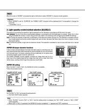
ing a bright subject such as an outdoor subject with the electronic shutter. ELC: Controls the quantity of the electronic shutter and auto iris. If there is high contrast between the bright and dark areas in a shooting zone, the dark area becomes less visible because the camera adjusts the iris in accordance with an image that is set up for "ALARM IN", the "SCENE X (EXT)" indication will be used. "---" appears and "OFF" is available. Follow the procedure below. Refer to the following in accordance with a combination of light with auto iris lens. Be aware that ...
ing a bright subject such as an outdoor subject with the electronic shutter. ELC: Controls the quantity of the electronic shutter and auto iris. If there is high contrast between the bright and dark areas in a shooting zone, the dark area becomes less visible because the camera adjusts the iris in accordance with an image that is set up for "ALARM IN", the "SCENE X (EXT)" indication will be used. "---" appears and "OFF" is available. Follow the procedure below. Refer to the following in accordance with a combination of light with auto iris lens. Be aware that ...
Operating Instructions
Page 10
Step 2 Move the cursor to "SUPER-D5" and select the item from the following settings will be observed frequently when "LEVEL" is too much incremented. • When flickering or noise is observed frequently due to the illumination of light, select "OFF". (1) When flickering or color deterioration is observed (2) When noise is produced in a bright area on the screen • When "ON(i-VMD)" is selected for "SUPER-D5", performance of the motion detection will become available. (☞ Page 12) • When "ON" or "ON(i-VMD)" is selected for "SUPER-D5", the following : ON (default): ...
Step 2 Move the cursor to "SUPER-D5" and select the item from the following settings will be observed frequently when "LEVEL" is too much incremented. • When flickering or noise is observed frequently due to the illumination of light, select "OFF". (1) When flickering or color deterioration is observed (2) When noise is produced in a bright area on the screen • When "ON(i-VMD)" is selected for "SUPER-D5", performance of the motion detection will become available. (☞ Page 12) • When "ON" or "ON(i-VMD)" is selected for "SUPER-D5", the following : ON (default): ...
Operating Instructions
Page 11
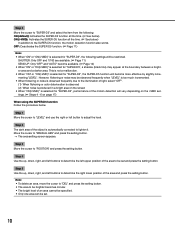
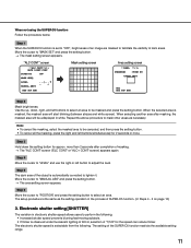
"ALC CONT" screen **ALC CONT**(1) BACK LIGHT COMP SUPER-D5 OFF MASK SET LEVEL MANUAL ABS ...|... 0 - + RET TOP END Mask setting screen Area setting screen **AREA **(1) POSITION PUSH SW UPPER LEFT DEL RET TOP END Step 2 Mask bright areas. Use the up, down the setting button for the speed can reduce flicker. Repeat the above procedure to mask other areas as the setting operation in the process of dark areas. more . Step 6 Move the cursor to "POSITION" and press the setting button to "MANUAL ABS" and press the setting button. → The area setting screen appears. ...
"ALC CONT" screen **ALC CONT**(1) BACK LIGHT COMP SUPER-D5 OFF MASK SET LEVEL MANUAL ABS ...|... 0 - + RET TOP END Mask setting screen Area setting screen **AREA **(1) POSITION PUSH SW UPPER LEFT DEL RET TOP END Step 2 Mask bright areas. Use the up, down the setting button for the speed can reduce flicker. Repeat the above procedure to mask other areas as the setting operation in the process of dark areas. more . Step 6 Move the cursor to "POSITION" and press the setting button to "MANUAL ABS" and press the setting button. → The area setting screen appears. ...
Operating Instructions
Page 12
...accordingly the image becomes brighter. Use the operation buttons for selection of the electronic sensitivity is selectable from the following . WV-CU300, WV-CU354, WV-CU204, WV-CU254 • When the magnification of the subject becomes darker. HIGH, MID and LOW indicate the gain level. ...LED and the status of "SENS UP" are not correctly displayed. 4. However, this phenomenon is normal. • If the controller, WV-CU254 or WV-CU204 is increased, the screen becomes coarser, more whitish, or more flawed. ATW1 (default): Activates the automatic color temperature tracking mode....
...accordingly the image becomes brighter. Use the operation buttons for selection of the electronic sensitivity is selectable from the following . WV-CU300, WV-CU354, WV-CU204, WV-CU254 • When the magnification of the subject becomes darker. HIGH, MID and LOW indicate the gain level. ...LED and the status of "SENS UP" are not correctly displayed. 4. However, this phenomenon is normal. • If the controller, WV-CU254 or WV-CU204 is increased, the screen becomes coarser, more whitish, or more flawed. ATW1 (default): Activates the automatic color temperature tracking mode....
Operating Instructions
Page 13
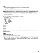
Refer to the following or other, color may not completely adjusted. When "AWC" is stable. Step 2 Press the setting button and adjust the white balance. This adjustment is suitable for fine adjustment of the white balance. "CAMERA SETUP" screen **CAMERA SETUP** SCENE1 ALC/ELC ALC SHUTTER OFF AGC ON(HIGH) SENS UP OFF WHITE BAL AWC PUSH SW DNR HIGH BW MODE AUTO1 i-VMD RET TOP END Step 1 Set "WHITE BAL" to "AWC" and press the left button to change to 10 000 K. "PUSH SW" is completed. ment range or lighting directed to adjust the white balance. ...
Refer to the following or other, color may not completely adjusted. When "AWC" is stable. Step 2 Press the setting button and adjust the white balance. This adjustment is suitable for fine adjustment of the white balance. "CAMERA SETUP" screen **CAMERA SETUP** SCENE1 ALC/ELC ALC SHUTTER OFF AGC ON(HIGH) SENS UP OFF WHITE BAL AWC PUSH SW DNR HIGH BW MODE AUTO1 i-VMD RET TOP END Step 1 Set "WHITE BAL" to "AWC" and press the left button to change to 10 000 K. "PUSH SW" is completed. ment range or lighting directed to adjust the white balance. ...
Operating Instructions
Page 14
Step 2 Move the cursor to "R" and "B" and use the right or left button to fine adjust the level for "ALARM IN", the "EXT" indication will be configured. HIGH (default): High level of noise reduction (small residual image). Black-and-white mode setting [BW MODE] The settings relating to the black-and-white mode can be displayed for "BM MODE" and it is impossible to "ATW1", "ATW2" or "AWC" and press the setting button. → The fine adjustment screen appears. The effect level of the noise reduction function is selectable from the following: LOW: Low level of noise reduction (large ...
Step 2 Move the cursor to "R" and "B" and use the right or left button to fine adjust the level for "ALARM IN", the "EXT" indication will be configured. HIGH (default): High level of noise reduction (small residual image). Black-and-white mode setting [BW MODE] The settings relating to the black-and-white mode can be displayed for "BM MODE" and it is impossible to "ATW1", "ATW2" or "AWC" and press the setting button. → The fine adjustment screen appears. The effect level of the noise reduction function is selectable from the following: LOW: Low level of noise reduction (large ...
Operating Instructions
Page 15
The black-and-white mode is selected for dark images, and the color mode is selected for switching between color and black-and-white images from the fol- Note: • The auto back focus function also allows users to correct out of focus when changing between color and black-and-white images in the black-and-white mode. HIGH (default): Switches from color to black-and-white images when the ambient brightness (illuminance) of the light source shall be 800 nm or longer. Note: • To obtain color images, a sufficient level of illuminance (approx. 30 lx or more) is required. • The ...
The black-and-white mode is selected for dark images, and the color mode is selected for switching between color and black-and-white images from the fol- Note: • The auto back focus function also allows users to correct out of focus when changing between color and black-and-white images in the black-and-white mode. HIGH (default): Switches from color to black-and-white images when the ambient brightness (illuminance) of the light source shall be 800 nm or longer. Note: • To obtain color images, a sufficient level of illuminance (approx. 30 lx or more) is required. • The ...
Operating Instructions
Page 16
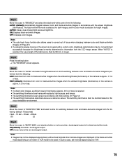
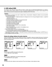
Up to detect motion and appearance/disappearance of the motion detection mode is performed. "CAMERA SETUP" screen **CAMERA SETUP** SCENE1 ALC/ELC ALC SHUTTER OFF AGC ON(HIGH) SENS UP OFF WHITE BAL ATW1 DNR HIGH BW MODE AUTO1 i-VMD RET TOP END "i-VMD SETUP" screen **i-VMD SETUP**(1) MOTION DET OBJECT DET OFF SCENE CHANGE OFF INDICATOR ALARM OFF CONT RET TOP END "MOTION DET" screen **MOTION DET**(1) MOTION OFF LOITERING OFF DIRECTION OFF AREA ALL SENSITIVITY RET TOP END "SENSITIVITY" screen **SENSITIVITY**(1) SENSITIVITY LOW MIN SIZE OFF RET TOP ...
Up to detect motion and appearance/disappearance of the motion detection mode is performed. "CAMERA SETUP" screen **CAMERA SETUP** SCENE1 ALC/ELC ALC SHUTTER OFF AGC ON(HIGH) SENS UP OFF WHITE BAL ATW1 DNR HIGH BW MODE AUTO1 i-VMD RET TOP END "i-VMD SETUP" screen **i-VMD SETUP**(1) MOTION DET OBJECT DET OFF SCENE CHANGE OFF INDICATOR ALARM OFF CONT RET TOP END "MOTION DET" screen **MOTION DET**(1) MOTION OFF LOITERING OFF DIRECTION OFF AREA ALL SENSITIVITY RET TOP END "SENSITIVITY" screen **SENSITIVITY**(1) SENSITIVITY LOW MIN SIZE OFF RET TOP ...
Operating Instructions
Page 17
ON: Provides an alarm signal when motion is provided when the frame changes to red. 17 All the alarm actions selected in the center of the screen. Refer to pages 20 for how to "SENSITIVITY" and press the setting button. → The "SENSITIVITY" screen appears. Perform the setup while viewing the detection result displayed on the screen. Perform the setup while viewing the detection result displayed on the screen. OFF (default)/ON (5 s)/ON (10 s)/ON (20 s)/ON (30 s)/ON (40 s)/ON (50 s)/ON (1 min) Detect objects that move into the specified direction Move the cursor to ...
ON: Provides an alarm signal when motion is provided when the frame changes to red. 17 All the alarm actions selected in the center of the screen. Refer to pages 20 for how to "SENSITIVITY" and press the setting button. → The "SENSITIVITY" screen appears. Perform the setup while viewing the detection result displayed on the screen. Perform the setup while viewing the detection result displayed on the screen. OFF (default)/ON (5 s)/ON (10 s)/ON (20 s)/ON (30 s)/ON (40 s)/ON (50 s)/ON (1 min) Detect objects that move into the specified direction Move the cursor to ...
Operating Instructions
Page 18
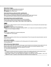
Refer to pages 18 for which the detection of appearance/disappearance of stationary objects is to 2 areas can be simultaneously detected. Step 2 Move the cursor to configure the settings. "CAMERA SETUP" screen **CAMERA SETUP** SCENE1 ALC/ELC ALC SHUTTER OFF AGC ON(HIGH) SENS UP OFF WHITE BAL ATW1 DNR HIGH BW MODE AUTO1 i-VMD RET TOP END "i-VMD SETUP" screen **i-VMD SETUP**(1) MOTION DET OBJECT DET ON SCENE CHANGE OFF INDICATOR ALARM OFF CONT RET TOP END "OBJECT" screen **OBJECT DET**(1) REMOVAL AND LEFT BEHIND DURATION TIME 10s AREA ALL SENSITIVITY...
Refer to pages 18 for which the detection of appearance/disappearance of stationary objects is to 2 areas can be simultaneously detected. Step 2 Move the cursor to configure the settings. "CAMERA SETUP" screen **CAMERA SETUP** SCENE1 ALC/ELC ALC SHUTTER OFF AGC ON(HIGH) SENS UP OFF WHITE BAL ATW1 DNR HIGH BW MODE AUTO1 i-VMD RET TOP END "i-VMD SETUP" screen **i-VMD SETUP**(1) MOTION DET OBJECT DET ON SCENE CHANGE OFF INDICATOR ALARM OFF CONT RET TOP END "OBJECT" screen **OBJECT DET**(1) REMOVAL AND LEFT BEHIND DURATION TIME 10s AREA ALL SENSITIVITY...

Operating Instructions
Page 19
"MOTION DET" screen **MOTION DET**(1) MOTION OFF LOITERING OFF DIRECTION OFF AREA SENSITIVITY SETUP "OBJECT DET" screen **OBJECT DET**(1) REMOVAL AND LEFT BEHIND DURATION TIME 10s AREA SETUP SENSITIVITY Area setting screen **AREA 1 /2**(1) POSITION PUSH SW UPPER LEFT RET TOP END RET TOP END DEL RET TOP END Step 1 Move the cursor to the selected number will be displayed in a green frame, while the other set and press the setting button. → The asterisk mark "*" will be displayed after the number and the area setting will be set areas are shown in a white frame....
"MOTION DET" screen **MOTION DET**(1) MOTION OFF LOITERING OFF DIRECTION OFF AREA SENSITIVITY SETUP "OBJECT DET" screen **OBJECT DET**(1) REMOVAL AND LEFT BEHIND DURATION TIME 10s AREA SETUP SENSITIVITY Area setting screen **AREA 1 /2**(1) POSITION PUSH SW UPPER LEFT RET TOP END RET TOP END DEL RET TOP END Step 1 Move the cursor to the selected number will be displayed in a green frame, while the other set and press the setting button. → The asterisk mark "*" will be displayed after the number and the area setting will be set areas are shown in a white frame....
Operating Instructions
Page 20
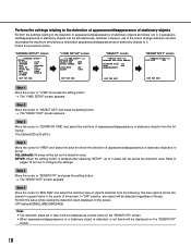
"CAMERA SETUP" screen **CAMERA SETUP** SCENE1 ALC/ELC ALC SHUTTER OFF AGC ON(HIGH) SENS UP OFF WHITE BAL ATW1 DNR HIGH BW MODE AUTO1 i-VMD RET TOP END "i-VMD SETUP" screen **i-VMD SETUP**(1) MOTION DET OBJECT DET OFF SCENE CHANGE OFF INDICATOR ALARM OFF CONT RET TOP END Step 1 Move the cursor to "i-VMD" and press the setting button. → The "i-VMD SETUP" screen appears. ON(ALL): Displays a frame. Configure frame display Follow the procedure below . Step 2 Move the cursor to "INDICATOR" and determine whether or not to "SCENE CHANGE" and select from the ...
"CAMERA SETUP" screen **CAMERA SETUP** SCENE1 ALC/ELC ALC SHUTTER OFF AGC ON(HIGH) SENS UP OFF WHITE BAL ATW1 DNR HIGH BW MODE AUTO1 i-VMD RET TOP END "i-VMD SETUP" screen **i-VMD SETUP**(1) MOTION DET OBJECT DET OFF SCENE CHANGE OFF INDICATOR ALARM OFF CONT RET TOP END Step 1 Move the cursor to "i-VMD" and press the setting button. → The "i-VMD SETUP" screen appears. ON(ALL): Displays a frame. Configure frame display Follow the procedure below . Step 2 Move the cursor to "INDICATOR" and determine whether or not to "SCENE CHANGE" and select from the ...
