Operation Manual
Page 6
... Units 64 Replacing Parts ...65 Replacing the Paper Feed Roller Module 65 Replacing the Double Feed Prevention Roller 69 Installing Optional Units 74 Installing the Imprinter Unit 74 Installing the Ink Cartridge 77 Removing the ink cartridge 79 Printing ...80 Appendix 81 Troubleshooting ...81 Shading Adjustment ...84 Repacking Instructions 85 Specifications...
... Units 64 Replacing Parts ...65 Replacing the Paper Feed Roller Module 65 Replacing the Double Feed Prevention Roller 69 Installing Optional Units 74 Installing the Imprinter Unit 74 Installing the Ink Cartridge 77 Removing the ink cartridge 79 Printing ...80 Appendix 81 Troubleshooting ...81 Shading Adjustment ...84 Repacking Instructions 85 Specifications...
Operation Manual
Page 15
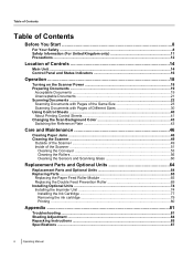
USB connector Operating Manual 15 Fan exhaust vent AC inlet Power cord Plugs may vary in shape depending on installing an imprinter, refer to "Installing the Imprinter Unit" (page 74). For details on country/area. Rear 1 2 3 4 5 Location of Controls Imprinter door You open this door when installing an imprinter unit (sold separately) or ink cartridge.
USB connector Operating Manual 15 Fan exhaust vent AC inlet Power cord Plugs may vary in shape depending on installing an imprinter, refer to "Installing the Imprinter Unit" (page 74). For details on country/area. Rear 1 2 3 4 5 Location of Controls Imprinter door You open this door when installing an imprinter unit (sold separately) or ink cartridge.
Operation Manual
Page 64
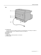
...Part Name Part Number Notes e m Roller exchange kit e • Paper feed roller n module KV-SS039 - For instructions on installation and removal, see "Installing the Imprinter Unit" (page 74). For instructions on installation, see "Installing the Ink Cartridge" (page 77...prevention P roller a r Replacement Parts Roller cleaning paper KV-SS03 See "About the roller cleaning paper" (page 51). t s a Ink cartridge n d O p t i Optional Units Imprinter unit o n a KV-SS021 KV-SS014 For optional imprinter unit. Includes 1 ink cartridge. Prints text and numbers ...
...Part Name Part Number Notes e m Roller exchange kit e • Paper feed roller n module KV-SS039 - For instructions on installation and removal, see "Installing the Imprinter Unit" (page 74). For instructions on installation, see "Installing the Ink Cartridge" (page 77...prevention P roller a r Replacement Parts Roller cleaning paper KV-SS03 See "About the roller cleaning paper" (page 51). t s a Ink cartridge n d O p t i Optional Units Imprinter unit o n a KV-SS021 KV-SS014 For optional imprinter unit. Includes 1 ink cartridge. Prints text and numbers ...
Operation Manual
Page 74
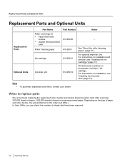
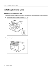
Open the imprinter door. 74 Operating Manual Set the power switch (A) of the document before scanning. The printed material will also be scanned. 1. Replacement Parts and Optional Units Installing Optional Units Installing the Imprinter Unit The imprinter prints on the face of the scanner to " " (OFF). 1 2.
Open the imprinter door. 74 Operating Manual Set the power switch (A) of the document before scanning. The printed material will also be scanned. 1. Replacement Parts and Optional Units Installing Optional Units Installing the Imprinter Unit The imprinter prints on the face of the scanner to " " (OFF). 1 2.

Operation Manual
Page 75
While keeping the direction of the imprinter as shown in the diagram below, insert the pins (A) on both sides into the guides, and insert the pins (B) on both sides into the guides until they are locked by the springs (C). 1 2 1 2 3 Operating Manual 75 Replacement Parts and Optional Units Notice • Be sure to correctly match the rib with the slot prior to inserting the connector. 4. Connect the cable. 3.
While keeping the direction of the imprinter as shown in the diagram below, insert the pins (A) on both sides into the guides, and insert the pins (B) on both sides into the guides until they are locked by the springs (C). 1 2 1 2 3 Operating Manual 75 Replacement Parts and Optional Units Notice • Be sure to correctly match the rib with the slot prior to inserting the connector. 4. Connect the cable. 3.

Operation Manual
Page 76
Set the power switch of the scanner to "Installing the Ink Cartridge" (page 77). 76 Operating Manual Note • For details on installing an ink cartridge, refer to " " (ON). Replacement Parts and Optional Units 5. Close the imprinter door. 6.
Set the power switch of the scanner to "Installing the Ink Cartridge" (page 77). 76 Operating Manual Note • For details on installing an ink cartridge, refer to " " (ON). Replacement Parts and Optional Units 5. Close the imprinter door. 6.
Operation Manual
Page 77
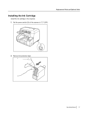
Operating Manual 77 Set the power switch (A) of the scanner to " " (OFF). Replacement Parts and Optional Units 1 2. Remove the protective tape. Installing the Ink Cartridge Install the ink cartridge in the imprinter. 1.
Operating Manual 77 Set the power switch (A) of the scanner to " " (OFF). Replacement Parts and Optional Units 1 2. Remove the protective tape. Installing the Ink Cartridge Install the ink cartridge in the imprinter. 1.
Operation Manual
Page 78
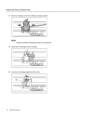
Lock the ink cartridge adjustment lever (A). 1 78 Operating Manual Notice • Adjust the position following the label on the imprinter. 4. Insert the ink cartridge into the carriage. 5. Replacement Parts and Optional Units 3. Move the carriage to the ink cartridge exchange position.
Lock the ink cartridge adjustment lever (A). 1 78 Operating Manual Notice • Adjust the position following the label on the imprinter. 4. Insert the ink cartridge into the carriage. 5. Replacement Parts and Optional Units 3. Move the carriage to the ink cartridge exchange position.

Operation Manual
Page 79
Set the power switch of the scanner to the ink cartridge exchange position. Remove the ink cartridge (A). 1 Operating Manual 79 Move the carriage to " " (OFF). 2. Removing the ink cartridge 1. Replacement Parts and Optional Units Notice • Adjust the position following the label on the imprinter. 3. Pinch the ink cartridge adjustment lever (A) and lift it. 1 4.
Set the power switch of the scanner to the ink cartridge exchange position. Remove the ink cartridge (A). 1 Operating Manual 79 Move the carriage to " " (OFF). 2. Removing the ink cartridge 1. Replacement Parts and Optional Units Notice • Adjust the position following the label on the imprinter. 3. Pinch the ink cartridge adjustment lever (A) and lift it. 1 4.
Operation Manual
Page 80
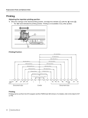
... desired printing position, and align the indicator (A) with the " " mark (B) . • The " " mark indicates the printing position. Replacement Parts and Optional Units Printing Adjusting the imprinter printing position 1.
... desired printing position, and align the indicator (A) with the " " mark (B) . • The " " mark indicates the printing position. Replacement Parts and Optional Units Printing Adjusting the imprinter printing position 1.
Operation Manual
Page 89
... tray 14 External dimensions 88 F Fan exhaust vent 15, 50 H Hard disk 4 Hopper 14 Hopper capacity 87 Hopper extension tray 14 I Image control 87 Imprinter door 15 Imprinter unit 64, 74 Ink cartridge 64, 77 Interface 4 J Joint 86 L Limit mark 25, 33 M Manual feed selector 14 Memory 4 O Operating Environment 88 Operating system...
... tray 14 External dimensions 88 F Fan exhaust vent 15, 50 H Hard disk 4 Hopper 14 Hopper capacity 87 Hopper extension tray 14 I Image control 87 Imprinter door 15 Imprinter unit 64, 74 Ink cartridge 64, 77 Interface 4 J Joint 86 L Limit mark 25, 33 M Manual feed selector 14 Memory 4 O Operating Environment 88 Operating system...