Installation Instructions
Page 1
INSTALLATION INSTRUCTIONS Ventilating Fan FV-05VS1 FV-08VS1 FV-10VS1 e Panasonid READ AND SAVE THESE INSTRUCTIONS. Table of Contents Supplied Accessories Description Dimensions Specifications Unpacking General Safety Information Wiring Diagram Installation I ( Joist Mounting-I ) Installation II ( ... 10-11 12 12 13 14 14-15 15-16 16 16 Please read these instructions carefully before attempting to install, operate or service the Panasonic Ventilating Fan.
INSTALLATION INSTRUCTIONS Ventilating Fan FV-05VS1 FV-08VS1 FV-10VS1 e Panasonid READ AND SAVE THESE INSTRUCTIONS. Table of Contents Supplied Accessories Description Dimensions Specifications Unpacking General Safety Information Wiring Diagram Installation I ( Joist Mounting-I ) Installation II ( ... 10-11 12 12 13 14 14-15 15-16 16 16 Please read these instructions carefully before attempting to install, operate or service the Panasonic Ventilating Fan.

Installation Instructions
Page 2
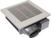
.... 2 A damper for safety. SUPPLIED ACCESSORIES FV-05VS1 FV-08VS1 FV-1OVS1 Part name Appearance Quantity Grille Long screw (ST4.2X20) Thumb screw Screw I (ST4.2X8) Screw II (ST4.2X10) Suspension bracket I 1 €) ) 6 O w. 1 E) ) 2 q) ) 2 .. 1 Suspension bracket II 1 Suspension 1 bracket III Spacer 1 DESCRIPTION These Panasonic ceiling /wall mount ventilation fans use a sirocco fan driven by a capacitor motor. It also...
.... 2 A damper for safety. SUPPLIED ACCESSORIES FV-05VS1 FV-08VS1 FV-1OVS1 Part name Appearance Quantity Grille Long screw (ST4.2X20) Thumb screw Screw I (ST4.2X8) Screw II (ST4.2X10) Suspension bracket I 1 €) ) 6 O w. 1 E) ) 2 q) ) 2 .. 1 Suspension bracket II 1 Suspension 1 bracket III Spacer 1 DESCRIPTION These Panasonic ceiling /wall mount ventilation fans use a sirocco fan driven by a capacitor motor. It also...
Installation Instructions
Page 3
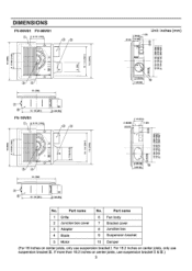
C> 5 13 (330) o li 1, - I0 5 4 13 (330) 3 0 N rC-O a 2 3/8 (60 1/2 (13) 1/2 (38 Unit: inches (mm) 1 (25) 8 9 3 1/8 78 3 6/8 (95) 7 6 L. 10 1/4 (261) FV-10VS1 (160 6 5/16 1 42) 3 3/4 (94 N N lb a ...... DIMENSIONS FV-05VS1 FV-08VS1 5/16 (160) 0 0 N N r-
C> 5 13 (330) o li 1, - I0 5 4 13 (330) 3 0 N rC-O a 2 3/8 (60 1/2 (13) 1/2 (38 Unit: inches (mm) 1 (25) 8 9 3 1/8 78 3 6/8 (95) 7 6 L. 10 1/4 (261) FV-10VS1 (160 6 5/16 1 42) 3 3/4 (94 N N lb a ...... DIMENSIONS FV-05VS1 FV-08VS1 5/16 (160) 0 0 N N r-
Installation Instructions
Page 4
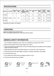
...) Noise (sones) Power consumption (W) Speed (rpm) Air,cdfem W liv)eer at 01.1" WG. ight lb.( kg) FV-05VS1 3 0.8 18 759 50 9.9 (4.5) FV-08VS1 Exhaust 120 60 3 1.4 26 FV-10VS1 4 1.5 34 Specifications are present. Do not install this ventilating fan where interior room temperature may exceed 104°F (40°C). 2. Follow all parts are based on...
...) Noise (sones) Power consumption (W) Speed (rpm) Air,cdfem W liv)eer at 01.1" WG. ight lb.( kg) FV-05VS1 3 0.8 18 759 50 9.9 (4.5) FV-08VS1 Exhaust 120 60 3 1.4 26 FV-10VS1 4 1.5 34 Specifications are present. Do not install this ventilating fan where interior room temperature may exceed 104°F (40°C). 2. Follow all parts are based on...
Installation Instructions
Page 5
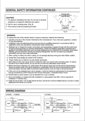
... Black Green Green White Black G een I Neutral > I Live -I > ' Earth Power supply AC120V 60Hz Earth ground Earth ground FV-10VS1 Fan Body Red Junction box Motor Capacitor White Black White Black White Black Thermally protected Green Green Green Neutral Live Earth Earth ground Earth ground ... fire-rated construction. 3. B) 3. When cutting or drilling into wall or ceiling, do not use to the manufacturer. 2. Install the fan at service panel and lock the service disconnecting means to the outdoors. 6. protected branch circuit. 10. To reduce the risk of fire or...
... Black Green Green White Black G een I Neutral > I Live -I > ' Earth Power supply AC120V 60Hz Earth ground Earth ground FV-10VS1 Fan Body Red Junction box Motor Capacitor White Black White Black White Black Thermally protected Green Green Green Neutral Live Earth Earth ground Earth ground ... fire-rated construction. 3. B) 3. When cutting or drilling into wall or ceiling, do not use to the manufacturer. 2. Install the fan at service panel and lock the service disconnecting means to the outdoors. 6. protected branch circuit. 10. To reduce the risk of fire or...
Installation Instructions
Page 6
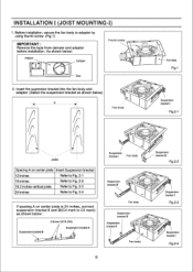
....1) IMPORTANT : Remove the tape from damper and adaptor before installation. Fan body Suspension bracket I Fig.2-3 Suspension bracket I ) 1. Before installation, secure the fan body to C4 mark) as shown below) A 4 ► Fan body Fan body Fig.1 Suspension bracket I Fan body Suspension bracket III Fig.2-2 Suspension bracketIII Fan body Suspension bracket III Suspension bracket II "dlielk4N. Insert the...
....1) IMPORTANT : Remove the tape from damper and adaptor before installation. Fan body Suspension bracket I Fig.2-3 Suspension bracket I ) 1. Before installation, secure the fan body to C4 mark) as shown below) A 4 ► Fan body Fan body Fig.1 Suspension bracket I Fan body Suspension bracket III Fig.2-2 Suspension bracketIII Fan body Suspension bracket III Suspension bracket II "dlielk4N. Insert the...
Installation Instructions
Page 7
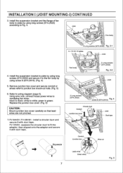
...joists by using long screws (ST4.2X20) according to the fan body by using screw II (ST4.2X10). (Fig. 4) 5. Refer to green; white to joists by using long screws (ST4.2X20) and secure it with duct tape. FV-10VS1: squeeze the circular duct to fit the adaptor, then ...slipped onto the adaptor and secure it to Fig. 3. INSTALLATION I (JOIST MOUNTING-I) CONTINUED 3. Joist Fan body 4 Long screws (ST4.2X20) Fig. 3-1 A = 10 1/4-12 inches Joist...
...joists by using long screws (ST4.2X20) according to the fan body by using screw II (ST4.2X10). (Fig. 4) 5. Refer to green; white to joists by using long screws (ST4.2X20) and secure it with duct tape. FV-10VS1: squeeze the circular duct to fit the adaptor, then ...slipped onto the adaptor and secure it to Fig. 3. INSTALLATION I (JOIST MOUNTING-I) CONTINUED 3. Joist Fan body 4 Long screws (ST4.2X20) Fig. 3-1 A = 10 1/4-12 inches Joist...

Installation Instructions
Page 8
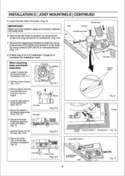
.... Finish ceiling work and wiring. 4. Ceiling hole should be aligned with the edge of Installation I ) CONTINUED 8. Insert the suspension bracket into fan body (refering to step 2 of the flange. (Fig. 6) 7ze 12 4-4°100(11"••• -410. 9. Adaptor 2. ...Disconnect plug connector from receptacle and remove adaptor from fan body before starting installation. Insert the suspension bracket into slots as shown below. Select the suspension bracket according to spacing D as shown and...
.... Finish ceiling work and wiring. 4. Ceiling hole should be aligned with the edge of Installation I ) CONTINUED 8. Insert the suspension bracket into fan body (refering to step 2 of the flange. (Fig. 6) 7ze 12 4-4°100(11"••• -410. 9. Adaptor 2. ...Disconnect plug connector from receptacle and remove adaptor from fan body before starting installation. Insert the suspension bracket into slots as shown below. Select the suspension bracket according to spacing D as shown and...
Installation Instructions
Page 9
...2 Long screws (ST4.2X20) Joist 9 9 Fig. 11 Remove adaptor from blower). (Fig. 12-1) 4 Screws 0 0 CI Adaptor 2. Insert fan body (without blower section) into the fan body. (Fig. 12-3) Fig.12-3 8. Secure the adaptor to joists as in vertical direction. (Fig. 11) 8. Loosen 4 screws (but ... using long screw (ST4.2X20). (Fig. 11) 7. Follow step 8 to complete the installation work. Insert the blower into joists. (Fig. 9) Fan body 5. When mounting body and blower separately 1. Secure the blower. (Fig. 12-4) and plug connector to receptacle. (Fig. 10) I I Circular...
...2 Long screws (ST4.2X20) Joist 9 9 Fig. 11 Remove adaptor from blower). (Fig. 12-1) 4 Screws 0 0 CI Adaptor 2. Insert fan body (without blower section) into the fan body. (Fig. 12-3) Fig.12-3 8. Secure the adaptor to joists as in vertical direction. (Fig. 11) 8. Loosen 4 screws (but ... using long screw (ST4.2X20). (Fig. 11) 7. Follow step 8 to complete the installation work. Insert the blower into joists. (Fig. 9) Fan body 5. When mounting body and blower separately 1. Secure the blower. (Fig. 12-4) and plug connector to receptacle. (Fig. 10) I I Circular...
Installation Instructions
Page 10
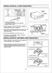
...to 9 of installation I (page 7, page 8) to adaptor by using thumb screw. (Fig. 1 of page 6) II 2. Before installation, secure the fan body to complete the installation work. Connect the ventilating fan to the frame hole.) 3. INSTALLATION M ( I-JOIST MOUNTING ) 4 kinds of I-joist inches (mm) hole mark 9/16 (14.3) C1 C 11... Long screws (ST4.2X20) Fig. 14 1. Insert the suspension bracket into the bracket cover of adaptor side and the back of the fan body. (Fig.15) (select the suspension bracket according to adaptor by checking I-joist size fix the screw to the I -joist. (Fig. 14) ...
...to 9 of installation I (page 7, page 8) to adaptor by using thumb screw. (Fig. 1 of page 6) II 2. Before installation, secure the fan body to complete the installation work. Connect the ventilating fan to the frame hole.) 3. INSTALLATION M ( I-JOIST MOUNTING ) 4 kinds of I-joist inches (mm) hole mark 9/16 (14.3) C1 C 11... Long screws (ST4.2X20) Fig. 14 1. Insert the suspension bracket into the bracket cover of adaptor side and the back of the fan body. (Fig.15) (select the suspension bracket according to adaptor by checking I-joist size fix the screw to the I -joist. (Fig. 14) ...
Installation Instructions
Page 11
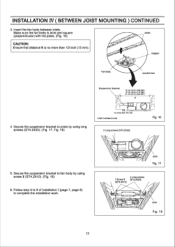
... 1/2 inch (13 mm). Follow step 5 to 9 of installation I (page 7, page 8) to fan body by using screw II (ST4.2X10). (Fig. 18) 6. Adaptor Fan body Junction box 4. INSTALLATION IV ( BETWEEN JOIST MOUNTING ) CONTINUED 3. Insert the fan body between joists. Make sure the fan body is level and square Joists (perpendicular) with the joists. (Fig. 16...
... 1/2 inch (13 mm). Follow step 5 to 9 of installation I (page 7, page 8) to fan body by using screw II (ST4.2X10). (Fig. 18) 6. Adaptor Fan body Junction box 4. INSTALLATION IV ( BETWEEN JOIST MOUNTING ) CONTINUED 3. Insert the fan body between joists. Make sure the fan body is level and square Joists (perpendicular) with the joists. (Fig. 16...
Installation Instructions
Page 12
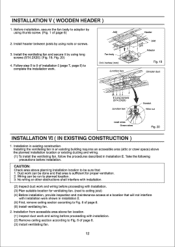
... area (attic or crawl space) above planning installation location to complete the installation work can be done and that area is sufficient for ventilating fan. (next to ceiling joist) (4) Before installation, provide inspection and maintenance access at a location that : 1. Wiring can be run to ...(ST4.2X20). (Fig. 19, Fig. 20) 4. Install the ventilating fan and secure it by using thumb screw. (Fig. 1 of page 8. (6) Install ventilating fan. 2. Installation from accessible area above fan location. (1) Inspect duct work and wiring before proceeding with installation work and ...
... area (attic or crawl space) above planning installation location to complete the installation work can be done and that area is sufficient for ventilating fan. (next to ceiling joist) (4) Before installation, provide inspection and maintenance access at a location that : 1. Wiring can be run to ...(ST4.2X20). (Fig. 19, Fig. 20) 4. Install the ventilating fan and secure it by using thumb screw. (Fig. 1 of page 8. (6) Install ventilating fan. 2. Installation from accessible area above fan location. (1) Inspect duct work and wiring before proceeding with installation work and ...
Installation Instructions
Page 13
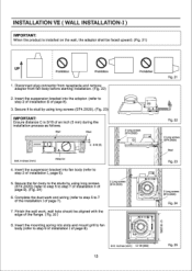
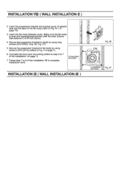
...is installed on the wall, the adaptor shall be aligned with the edge of the flange. ( Fig. 25 ) 8. A Stud A,- Insert the mounting spring into fan body (refer to step 7 of installation II of page 8). 1 111 1141 0 0 ) Unit: inches (mm) 12 1/8 (305) CO 0 01 Fig....(ST4.2X20) I- INSTALLATION VII ( WALL INSTALLATION-I ) IMPORTANT: When the product is 3/16 of page 8). O 3. Insert the suspension bracket into slots and mount grill to fan body (refer to 7 of the installation I of installation I of page 9). (Fig. 24) 6. Fig. 23 4. Wall Stud III C 3/16 (5) Unit: inches (...
...is installed on the wall, the adaptor shall be aligned with the edge of the flange. ( Fig. 25 ) 8. A Stud A,- Insert the mounting spring into fan body (refer to step 7 of installation II of page 8). 1 111 1141 0 0 ) Unit: inches (mm) 12 1/8 (305) CO 0 01 Fig....(ST4.2X20) I- INSTALLATION VII ( WALL INSTALLATION-I ) IMPORTANT: When the product is 3/16 of page 8). O 3. Insert the suspension bracket into slots and mount grill to fan body (refer to 7 of the installation I of installation I of page 9). (Fig. 24) 6. Fig. 23 4. Wall Stud III C 3/16 (5) Unit: inches (...
Installation Instructions
Page 14
...5. Ensure that distance C 3/16 inch (5mm). 4. Secure the suspension bracket to Fig.15-1 of page 7). 7. Make sure the fan body is level and square(prependicular) with the stud. Complete the duct work and wiring (refere to step 5 to complete installation work....) Fig. 26 i / ®I of page 10). 3. INSTALLATION Vi ( WALL INSTALLATION-II ) 2. Insert the fan body between studs. Follow step 7 to 8 of the installation VII to 7 of page 7). 6. Secure the suspension bracket to fan body by using / screw If (ST4.2X10) (refere to Fig. 4 of the installation I / 0 . &#...
...5. Ensure that distance C 3/16 inch (5mm). 4. Secure the suspension bracket to Fig.15-1 of page 7). 7. Make sure the fan body is level and square(prependicular) with the stud. Complete the duct work and wiring (refere to step 5 to complete installation work....) Fig. 26 i / ®I of page 10). 3. INSTALLATION Vi ( WALL INSTALLATION-II ) 2. Insert the fan body between studs. Follow step 7 to 8 of the installation VII to 7 of page 7). 6. Secure the suspension bracket to fan body by using / screw If (ST4.2X10) (refere to Fig. 4 of the installation I / 0 . &#...
Installation Instructions
Page 15
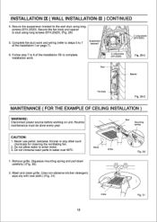
... of the installation VII to complete installation work. Glove l Grille 1. Never use petrol, benzene, thinner or any other such chemicals for cleaning the ventilating fan. 2. Remove grille. (Squeeze mounting spring and pull down carefully.) (Fig. 30) 2. Routine maintenance must be done every year. Do not allow water ... (ST4.2X20). (Fig. 29) 5. Slot Mounting spring CAUTION: 1. Follow step 7 to stud using long screws (ST4.2X20). Secure the fan body and spacer to 8 of the installation I 0 a 0 2 Long screws (ST4.2X20) 2 Long screws (ST4.2X20) Fig. 29-2 Stud Spacer...
... of the installation VII to complete installation work. Glove l Grille 1. Never use petrol, benzene, thinner or any other such chemicals for cleaning the ventilating fan. 2. Remove grille. (Squeeze mounting spring and pull down carefully.) (Fig. 30) 2. Routine maintenance must be done every year. Do not allow water ... (ST4.2X20). (Fig. 29) 5. Slot Mounting spring CAUTION: 1. Follow step 7 to stud using long screws (ST4.2X20). Secure the fan body and spacer to 8 of the installation I 0 a 0 2 Long screws (ST4.2X20) 2 Long screws (ST4.2X20) Fig. 29-2 Stud Spacer...
Installation Instructions
Page 16
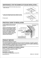
... to Customer call 1-866-292-7292 to ensure a minimum of North America, One Panasonic Way, Secaucus, NJ 07094 www.panasonic.com PANASONIC CANADA INC. 5770 Ambler Drive, Mississauga, ON L4W 2T3 www.panasonic.ca X0606-4049 08VS10420F Caulk termination to drywall. Foil tape tightly covers all flex joints...a vacuum cleaner. (Fig. 32) 4. MAINTENANCE ( FOR THE EXAMPLE OF CEILING INSTALLATION ) 3. Remove dust and dirt from fan body. Panasonic fans and fan/light combination units do not create enough ambient heat to be subjected to minimize building heat loss and gain. (Fig. 34)...
... to Customer call 1-866-292-7292 to ensure a minimum of North America, One Panasonic Way, Secaucus, NJ 07094 www.panasonic.com PANASONIC CANADA INC. 5770 Ambler Drive, Mississauga, ON L4W 2T3 www.panasonic.ca X0606-4049 08VS10420F Caulk termination to drywall. Foil tape tightly covers all flex joints...a vacuum cleaner. (Fig. 32) 4. MAINTENANCE ( FOR THE EXAMPLE OF CEILING INSTALLATION ) 3. Remove dust and dirt from fan body. Panasonic fans and fan/light combination units do not create enough ambient heat to be subjected to minimize building heat loss and gain. (Fig. 34)...
