
Installation Instructions
Page 1
... injury and/or property damage. Failure to install, operate or service the Panasonic Ventilating Fan. I (Joist Mounting - Please retain this booklet for having purchased our Ventilating Fan. II) 8 Maintenance (Cleaning) 8-9 Practical Guide To Installation 9 Specifications 10 Product Service 10 FV-05VQ5 FV-08VQ 5 FV-11VQ5 FV-15VQ 5 0 6 0 READ AND SAVE THESE INSTRUCTIONS Thank you very much for...
... injury and/or property damage. Failure to install, operate or service the Panasonic Ventilating Fan. I (Joist Mounting - Please retain this booklet for having purchased our Ventilating Fan. II) 8 Maintenance (Cleaning) 8-9 Practical Guide To Installation 9 Specifications 10 Product Service 10 FV-05VQ5 FV-08VQ 5 FV-11VQ5 FV-15VQ 5 0 6 0 READ AND SAVE THESE INSTRUCTIONS Thank you very much for...

Installation Instructions
Page 2
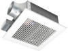
...--._ Installation ,: instructions 2 Warranty 1 sheet DESCRIPTION These Panasonic ventilating fan models are present. The grille covering the fan body is provided. UNPACKING Unpack and carefully remove the unit from carton. E78414. These Panasonic ventilating fan models use a sirocco fan driven by UL under UL file No. The motor is... designed to reduce the noise level. 2 The blower uses a high-capacity sirocco fan developed to have an extended service ...
...--._ Installation ,: instructions 2 Warranty 1 sheet DESCRIPTION These Panasonic ventilating fan models are present. The grille covering the fan body is provided. UNPACKING Unpack and carefully remove the unit from carton. E78414. These Panasonic ventilating fan models use a sirocco fan driven by UL under UL file No. The motor is... designed to reduce the noise level. 2 The blower uses a high-capacity sirocco fan developed to have an extended service ...

Installation Instructions
Page 3
...of Heating, Refrigeration, and Air Conditioning Engineers (ASHRAE) and the local code authorities. 5. Protect the power cord from being switched on or near the fan, motor, junction box. 5. Do not kink the power cord. 7. A. 8. Do not use only. B WARNING: To reduce the risk of... for installation in Canada only) 3 Follow the heating equipment manufacturer's guideline and safety standards such as those published by the manufacturer. Ducted fans must be marked as a tag, to prevent back drafting. These models are configured as the National Electrical Code (NEC) and the Occupation...
...of Heating, Refrigeration, and Air Conditioning Engineers (ASHRAE) and the local code authorities. 5. Protect the power cord from being switched on or near the fan, motor, junction box. 5. Do not kink the power cord. 7. A. 8. Do not use only. B WARNING: To reduce the risk of... for installation in Canada only) 3 Follow the heating equipment manufacturer's guideline and safety standards such as those published by the manufacturer. Ducted fans must be marked as a tag, to prevent back drafting. These models are configured as the National Electrical Code (NEC) and the Occupation...

Installation Instructions
Page 4
... DIAGRAM Red Motor White White Capacitor Black (Fuse in square brackets refer to FV-15VQ5 which are different from FV-05/08/11VQ5) No. Earth Eound _ Earth ground Junction box Fan body AP r1;0r Vuar Eliyz 4 DIMENSIONS FV-05VQ5 FV-08VQ5 FV-11VQ5 FV-15VQ5 2 1 3 gg, 0 13 (830) 8 10 1/4 (260) 3 1/2 (90) 3 7/8 (100)] 7/8 (22 5) 1 (26) 4 3/5 (116) 51/8 130...
... DIAGRAM Red Motor White White Capacitor Black (Fuse in square brackets refer to FV-15VQ5 which are different from FV-05/08/11VQ5) No. Earth Eound _ Earth ground Junction box Fan body AP r1;0r Vuar Eliyz 4 DIMENSIONS FV-05VQ5 FV-08VQ5 FV-11VQ5 FV-15VQ5 2 1 3 gg, 0 13 (830) 8 10 1/4 (260) 3 1/2 (90) 3 7/8 (100)] 7/8 (22 5) 1 (26) 4 3/5 (116) 51/8 130...

Installation Instructions
Page 5
... 1/2 (540-597) Suspension bracket II Screw I Suspension bracket I Fig.1 2. As shown below . Insert the suspension bracket I and II into the fan body. (Select the suspension bracket connection holes as shown below) (Fig.1) Suspension bracket connect method: Suspension bracket I and II connect with screw I as...screws (ST4.2X20) Joist O 2 Long screws (ST4.2X20) Screw II (ST4.2X14) Fig.2 5 Install the suspension bracket and the flange of fan body to joists by using screw II (ST4.2X14). (Fig.2) V Suspension bracket I (JOIST MOUNTING - I) A Joist situation: Spacing A is 16 inches ...
... 1/2 (540-597) Suspension bracket II Screw I Suspension bracket I Fig.1 2. As shown below . Insert the suspension bracket I and II into the fan body. (Select the suspension bracket connection holes as shown below) (Fig.1) Suspension bracket connect method: Suspension bracket I and II connect with screw I as...screws (ST4.2X20) Joist O 2 Long screws (ST4.2X20) Screw II (ST4.2X14) Fig.2 5 Install the suspension bracket and the flange of fan body to joists by using screw II (ST4.2X14). (Fig.2) V Suspension bracket I (JOIST MOUNTING - I) A Joist situation: Spacing A is 16 inches ...

Installation Instructions
Page 6
... (Fuse in motor) Fuse type: FV-05VQ5: 237 .F (114 °C) FV-08VQ5: 237 f (114 °C) FV-11VQ5: 237 F (114 °C) FV-15VQ5: 273 °F (134 °C) 6r_ee,n, Earth ground Neutral Power Live (Vent.) Supply AC 120V Earth ground > 80Hz Junction box Fan body r. Finish ceiling work. Grille ...cause harmonic distortion which can cause a motor humming noise. Remove junction box cover and secure conduit or stress relief to black (Ventilating fan) Fig.4 Ceiling 7. Refer to wiring diagram below : Tapes O 1 After finishing the ceiling job, fill gap between flange and ...
... (Fuse in motor) Fuse type: FV-05VQ5: 237 .F (114 °C) FV-08VQ5: 237 f (114 °C) FV-11VQ5: 237 F (114 °C) FV-15VQ5: 273 °F (134 °C) 6r_ee,n, Earth ground Neutral Power Live (Vent.) Supply AC 120V Earth ground > 80Hz Junction box Fan body r. Finish ceiling work. Grille ...cause harmonic distortion which can cause a motor humming noise. Remove junction box cover and secure conduit or stress relief to black (Ventilating fan) Fig.4 Ceiling 7. Refer to wiring diagram below : Tapes O 1 After finishing the ceiling job, fill gap between flange and ...

Installation Instructions
Page 7
...). (Fig.9) Suspension bracket III 16 inches (406 mm) or 19 inches (483 mm) horizental joist Suspension bracket IV 24 inches (609 mm) horizental joist Joists 4 Fan body 6 Long screws (ST4.2X20) 13 1/4-15 1/2 (336-394 ) 16 1/2-18 3/4 (419-480) 21 1/4-23 1/2 ( 540-597 ) A 2 1/2-4 1/5 (64-107) 51/2-7 1/5 (140-183... (609 mm) on center joists, please follow the installation step as shown below . Insert the suspension bracket I and II into the fan body and suspension bracket III or IV into the adaptor. (Select the suspension bracket connection holes as shown below) (Fig.7, Fig.8) Suspension...
...). (Fig.9) Suspension bracket III 16 inches (406 mm) or 19 inches (483 mm) horizental joist Suspension bracket IV 24 inches (609 mm) horizental joist Joists 4 Fan body 6 Long screws (ST4.2X20) 13 1/4-15 1/2 (336-394 ) 16 1/2-18 3/4 (419-480) 21 1/4-23 1/2 ( 540-597 ) A 2 1/2-4 1/5 (64-107) 51/2-7 1/5 (140-183... (609 mm) on center joists, please follow the installation step as shown below . Insert the suspension bracket I and II into the fan body and suspension bracket III or IV into the adaptor. (Select the suspension bracket connection holes as shown below) (Fig.7, Fig.8) Suspension...

Installation Instructions
Page 8
...(266 mm) to complete the installation work . Never use gasoline, benzene, thinner or any other such chemicals for cleaning the ventilating fan. 2. INSTALLATION II (SUSPENSION BRACKETS MOUNTING) CONTINUED 4. Slot Mounting spring CAUTION: 1. Do not soak resin parts in water when cleaning. 3. Joist... Fan body 4 Long screws (ST4.2X20) Fig.10 MAINTENANCE (CLEANING) WARNING: Disconnect power source before working on unit. Secure 4 long ...
...(266 mm) to complete the installation work . Never use gasoline, benzene, thinner or any other such chemicals for cleaning the ventilating fan. 2. INSTALLATION II (SUSPENSION BRACKETS MOUNTING) CONTINUED 4. Slot Mounting spring CAUTION: 1. Do not soak resin parts in water when cleaning. 3. Joist... Fan body 4 Long screws (ST4.2X20) Fig.10 MAINTENANCE (CLEANING) WARNING: Disconnect power source before working on unit. Secure 4 long ...

Installation Instructions
Page 9
... elbow In attic installation, caulk box to termination and seal with clean cloth) (Fig.12) 3. The grille should be placed directly over the fan housing in the attic. Replace grille. Four inch or six inch roof jack, wall cap, or soffit vent with backdraft damper Mechanically connect duct ...mastic or approved foil faced tape at all flex joints Insulation Foil tape tightly covers all metal duct joints (glue PVC joints) Fig.15 9 Panasonic fans and fan/light combination units do not create enough ambient heat to be subjected to minimize building heat loss and gain. (Fig. 15) Loose fill ...
... elbow In attic installation, caulk box to termination and seal with clean cloth) (Fig.12) 3. The grille should be placed directly over the fan housing in the attic. Replace grille. Four inch or six inch roof jack, wall cap, or soffit vent with backdraft damper Mechanically connect duct ...mastic or approved foil faced tape at all flex joints Insulation Foil tape tightly covers all metal duct joints (glue PVC joints) Fig.15 9 Panasonic fans and fan/light combination units do not create enough ambient heat to be subjected to minimize building heat loss and gain. (Fig. 15) Loose fill ...

