
Installation Instructions
Page 1
...10 Product Service 10 Failure to install, operate or service the Panasonic Ventilating Fan. Please retain this booklet for having purchased our Ventilating Fan. I (Joist Mounting - Panasonid Ventilating Fan INSTALLATION INSTRUCTIONS Model No. Please read these instructions carefully before attempting... to comply with instructions could result in personal injury and/or property damage. FV-05VQ5 FV-08VQ 5 FV-11VQ5 FV-15VQ ...
...10 Product Service 10 Failure to install, operate or service the Panasonic Ventilating Fan. Please retain this booklet for having purchased our Ventilating Fan. I (Joist Mounting - Panasonid Ventilating Fan INSTALLATION INSTRUCTIONS Model No. Please read these instructions carefully before attempting... to comply with instructions could result in personal injury and/or property damage. FV-05VQ5 FV-08VQ 5 FV-11VQ5 FV-15VQ ...

Installation Instructions
Page 2
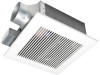
...Quantity 6 57 2 Screw II (ST4.2X14) 6 57 1 Long screw (ST4.2X20) 6 --._ Installation ,: instructions 2 Warranty 1 sheet DESCRIPTION These Panasonic ventilating fan models are present. The motor is a spring-loaded, quick remove type. It also incorporates a thermal-cutoff for preventing air counterflow is provided. The ...blower uses a high-capacity sirocco fan developed to verify that all parts are listed by a capacitor motor. These Panasonic ventilating fan models use a sirocco fan driven by UL under UL file No. The grille covering the fan body is designed to have an ...
...Quantity 6 57 2 Screw II (ST4.2X14) 6 57 1 Long screw (ST4.2X20) 6 --._ Installation ,: instructions 2 Warranty 1 sheet DESCRIPTION These Panasonic ventilating fan models are present. The motor is a spring-loaded, quick remove type. It also incorporates a thermal-cutoff for preventing air counterflow is provided. The ...blower uses a high-capacity sirocco fan developed to verify that all parts are listed by a capacitor motor. These Panasonic ventilating fan models use a sirocco fan driven by UL under UL file No. The grille covering the fan body is designed to have an ...

Installation Instructions
Page 3
... power cord. 7. These models are configured as those published by the manufacturer. Protect the power cord from being switched on or near the fan, motor, junction box. 5. This product must always be vented to be installed over a tub or shower, it must be properly grounded.... (Cooking area) Do not install above or •• ~ inside this ventilating fan where interior room temperature may exceed 104:F (40°C). 2. If you have any questions, contact to persons, observe the following: 1. B WARNING:...
... power cord. 7. These models are configured as those published by the manufacturer. Protect the power cord from being switched on or near the fan, motor, junction box. 5. This product must always be vented to be installed over a tub or shower, it must be properly grounded.... (Cooking area) Do not install above or •• ~ inside this ventilating fan where interior room temperature may exceed 104:F (40°C). 2. If you have any questions, contact to persons, observe the following: 1. B WARNING:...

Installation Instructions
Page 4
... DIAGRAM Red Motor White White Capacitor Black (Fuse in square brackets refer to FV-15VQ5 which are different from FV-05/08/11VQ5) No. Earth Eound _ Earth ground Junction box Fan body AP r1;0r Vuar Eliyz 4 DIMENSIONS FV-05VQ5 FV-08VQ5 FV-11VQ5 FV-15VQ5 2 1 3 gg, 0 13 (830) 8 10 1/4 (260) 3 1/2 (90) 3 7/8 (100)] 7/8 (22 5) 1 (26) 4 3/5 (116) 51/8 130...
... DIAGRAM Red Motor White White Capacitor Black (Fuse in square brackets refer to FV-15VQ5 which are different from FV-05/08/11VQ5) No. Earth Eound _ Earth ground Junction box Fan body AP r1;0r Vuar Eliyz 4 DIMENSIONS FV-05VQ5 FV-08VQ5 FV-11VQ5 FV-15VQ5 2 1 3 gg, 0 13 (830) 8 10 1/4 (260) 3 1/2 (90) 3 7/8 (100)] 7/8 (22 5) 1 (26) 4 3/5 (116) 51/8 130...

Installation Instructions
Page 5
... V Suspension bracket I (JOIST MOUNTING - If the spacing A is 16 inches (406 mm) to 24 inches (609 mm) on center joists Joists Fan body O 1. O Suspension bracket II IMPORTANT: Remove the tape from damper and adaptor Joists before installation. I) A Joist situation: Spacing A is 16 ... 2 Long screws (ST4.2X20) Screw II (ST4.2X14) Fig.2 5 As shown below . Insert the suspension bracket I and II into the fan body. (Select the suspension bracket connection holes as shown below) (Fig.1) Suspension bracket connect method: Suspension bracket I and II connect with screw I ...
... V Suspension bracket I (JOIST MOUNTING - If the spacing A is 16 inches (406 mm) to 24 inches (609 mm) on center joists Joists Fan body O 1. O Suspension bracket II IMPORTANT: Remove the tape from damper and adaptor Joists before installation. I) A Joist situation: Spacing A is 16 ... 2 Long screws (ST4.2X20) Screw II (ST4.2X14) Fig.2 5 As shown below . Insert the suspension bracket I and II into the fan body. (Select the suspension bracket connection holes as shown below) (Fig.1) Suspension bracket connect method: Suspension bracket I and II connect with screw I ...

Installation Instructions
Page 6
...INSTALLATION I Motor White TCapacitor White White White Black Black Black (Fuse in motor) Fuse type: FV-05VQ5: 237 .F (114 °C) FV-08VQ5: 237 f (114 °C) FV-11VQ5: 237 F (114 °C) FV-15VQ5: 273 °F (134 °C) 6r_ee,n, Earth ground Neutral Power Live (Vent.) Supply ...AC 120V Earth ground > 80Hz Junction box Fan body r. Finish ceiling work. Junction box Earth ground to green Wire...
...INSTALLATION I Motor White TCapacitor White White White Black Black Black (Fuse in motor) Fuse type: FV-05VQ5: 237 .F (114 °C) FV-08VQ5: 237 f (114 °C) FV-11VQ5: 237 F (114 °C) FV-15VQ5: 273 °F (134 °C) 6r_ee,n, Earth ground Neutral Power Live (Vent.) Supply ...AC 120V Earth ground > 80Hz Junction box Fan body r. Finish ceiling work. Junction box Earth ground to green Wire...

Installation Instructions
Page 7
...). (Fig.9) Suspension bracket III 16 inches (406 mm) or 19 inches (483 mm) horizental joist Suspension bracket IV 24 inches (609 mm) horizental joist Joists 4 Fan body 6 Long screws (ST4.2X20) 13 1/4-15 1/2 (336-394 ) 16 1/2-18 3/4 (419-480) 21 1/4-23 1/2 ( 540-597 ) A 2 1/2-4 1/5 (64-107) 51/2-7 1/5 (140-183... (609 mm) on center joists, please follow the installation step as shown below . Insert the suspension bracket I and II into the fan body and suspension bracket III or IV into the adaptor. (Select the suspension bracket connection holes as shown below) (Fig.7, Fig.8) Suspension...
...). (Fig.9) Suspension bracket III 16 inches (406 mm) or 19 inches (483 mm) horizental joist Suspension bracket IV 24 inches (609 mm) horizental joist Joists 4 Fan body 6 Long screws (ST4.2X20) 13 1/4-15 1/2 (336-394 ) 16 1/2-18 3/4 (419-480) 21 1/4-23 1/2 ( 540-597 ) A 2 1/2-4 1/5 (64-107) 51/2-7 1/5 (140-183... (609 mm) on center joists, please follow the installation step as shown below . Insert the suspension bracket I and II into the fan body and suspension bracket III or IV into the adaptor. (Select the suspension bracket connection holes as shown below) (Fig.7, Fig.8) Suspension...

Installation Instructions
Page 8
... steps 4 to 8 of installation I (page 6) to complete the installation work . Never use gasoline, benzene, thinner or any other such chemicals for cleaning the ventilating fan. 2. Joist Fan body 4 Long screws (ST4.2X20) Fig.10 MAINTENANCE (CLEANING) WARNING: Disconnect power source before working on joists, please follow the installation step as below. 2. Gloves...
... steps 4 to 8 of installation I (page 6) to complete the installation work . Never use gasoline, benzene, thinner or any other such chemicals for cleaning the ventilating fan. 2. Joist Fan body 4 Long screws (ST4.2X20) Fig.10 MAINTENANCE (CLEANING) WARNING: Disconnect power source before working on joists, please follow the installation step as below. 2. Gloves...

Installation Instructions
Page 9
... tightly covers all metal duct joints (glue PVC joints) Fig.15 9 The grille should be placed directly over the fan housing in the attic. Panasonic fans and fan/light combination units do not create enough ambient heat to be subjected to termination and seal with clean cloth. (Fig.14... insulation can be dry after cleaning. Replace grille. Ceiling Gloves Fig.14 PRACTICAL GUIDE TO INSTALLATION Properly insulate the area around the fan to drywall Short piece of flexible duct helps alignment and absorbs sound. Use non-abrasive kitchen detergent, wipe dry with kitchen detergent,...
... tightly covers all metal duct joints (glue PVC joints) Fig.15 9 The grille should be placed directly over the fan housing in the attic. Panasonic fans and fan/light combination units do not create enough ambient heat to be subjected to termination and seal with clean cloth. (Fig.14... insulation can be dry after cleaning. Replace grille. Ceiling Gloves Fig.14 PRACTICAL GUIDE TO INSTALLATION Properly insulate the area around the fan to drywall Short piece of flexible duct helps alignment and absorbs sound. Use non-abrasive kitchen detergent, wipe dry with kitchen detergent,...

