
AJSDC915 User Guide
Page 1
P Printed in Japan F0802H D VQT0A45 Model No. P Before operating this product, please read the instructions carefully and save this manual for future use. Digital Camera/VTR Operating Instructions AJ-
P Printed in Japan F0802H D VQT0A45 Model No. P Before operating this product, please read the instructions carefully and save this manual for future use. Digital Camera/VTR Operating Instructions AJ-
AJSDC915 User Guide
Page 3
...Changing the Display Mode 62 ÁSetting the Marker Displays 62 ÁSetting the Camera ID 63 Displays ÁRemaining Battery Level and Audio Level Displays 64 ÁVTR Section Operation/Status-Related Displays 64 ÁTime Code-Related Displays 65 Adjusting the ...be set or adjusted immediately after purchase. -3- Contents For your safety 2 General and Features 5 ÁFeatures of the Camera Section . . . . . 5 ÁFeatures of the VTR Section 8 System Configuration 9 Controls and Their Functions ÁPower Supply Section 10 ÁAccessory Mounting Section 11 ÁAudio...
...Changing the Display Mode 62 ÁSetting the Marker Displays 62 ÁSetting the Camera ID 63 Displays ÁRemaining Battery Level and Audio Level Displays 64 ÁVTR Section Operation/Status-Related Displays 64 ÁTime Code-Related Displays 65 Adjusting the ...be set or adjusted immediately after purchase. -3- Contents For your safety 2 General and Features 5 ÁFeatures of the Camera Section . . . . . 5 ÁFeatures of the VTR Section 8 System Configuration 9 Controls and Their Functions ÁPower Supply Section 10 ÁAccessory Mounting Section 11 ÁAudio...
AJSDC915 User Guide
Page 4
...193;MAIN menu screen 2 of 4 (SUB menus 121 VF DISPLAY (121), VF INDICATOR (123), CAMERA ID (124), SHUTTER SPEED (124), SYNCHRO SCAN (125), !LED (125), CAMERA SW MODE (126), SUPER GAIN (127), VTR FUNCTION (128), BATT/TAPE ALARM (130) ÁMAIN menu screen 3 of 4 (SUB menus ...Inspection Preparations 153 ÁInspecting the Camera Section 153 ÁInspecting the Viewfinder 154 ÁInspecting the Iris and Zoom Functions 155 ÁInspecting the VTR Section 155 Specifications ÁGeneral 157 ÁCamera Section 157 ÁViewfinder 157 ÁVTR Section 158 ÁAccessories 158 ...
...193;MAIN menu screen 2 of 4 (SUB menus 121 VF DISPLAY (121), VF INDICATOR (123), CAMERA ID (124), SHUTTER SPEED (124), SYNCHRO SCAN (125), !LED (125), CAMERA SW MODE (126), SUPER GAIN (127), VTR FUNCTION (128), BATT/TAPE ALARM (130) ÁMAIN menu screen 3 of 4 (SUB menus ...Inspection Preparations 153 ÁInspecting the Camera Section 153 ÁInspecting the Viewfinder 154 ÁInspecting the Iris and Zoom Functions 155 ÁInspecting the VTR Section 155 Specifications ÁGeneral 157 ÁCamera Section 157 ÁViewfinder 157 ÁVTR Section 158 ÁAccessories 158 ...
AJSDC915 User Guide
Page 5
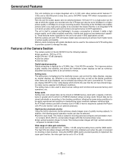
... from p3 dB to the user's convenience. Not only can the screen aspect ratio be used for the ! Both the camera unit and VTR unit feature digital signal processing to standard mode. lamp display which provides all the optimum functions and performance for a longer recording duration. tor ...be set to 30 or 36 dB. -5- General and Features This unit combines as setup cards. For example, display ON/OFF for the camera and VTR setting data to provide a system to menus. Memory cards complying with a very high picture quality to PCMCIA standard ratings as a single integrated...
... from p3 dB to the user's convenience. Not only can the screen aspect ratio be used for the ! Both the camera unit and VTR unit feature digital signal processing to standard mode. lamp display which provides all the optimum functions and performance for a longer recording duration. tor ...be set to 30 or 36 dB. -5- General and Features This unit combines as setup cards. For example, display ON/OFF for the camera and VTR setting data to provide a system to menus. Memory cards complying with a very high picture quality to PCMCIA standard ratings as a single integrated...
AJSDC915 User Guide
Page 6
... status The unit informs of VTR trouble, the end of the tape, battery wear, etc. Character display function The unit is turned on. on the viewfinder screen. Generation of SMPTE/SNG color bar and reference audio signals The camera section contains a circuit which generates an SMPTE ... unit's power supply, the remaining battery level can be displayed numerically on the viewfinder screen. In addition, when using an Anton Bauer Digital Magnum series battery as standard equipment. Four filter disks as standard equipment CC (color temperature conversion) and ND (neutral density) filters are...
... status The unit informs of VTR trouble, the end of the tape, battery wear, etc. Character display function The unit is turned on. on the viewfinder screen. Generation of SMPTE/SNG color bar and reference audio signals The camera section contains a circuit which generates an SMPTE ... unit's power supply, the remaining battery level can be displayed numerically on the viewfinder screen. In addition, when using an Anton Bauer Digital Magnum series battery as standard equipment. Four filter disks as standard equipment CC (color temperature conversion) and ND (neutral density) filters are...

AJSDC915 User Guide
Page 7
Remote control Connecting the Extension Control Unit (option, AJ-EC3) allows a portion of the camera section functions to the main unit using the 26-pin/12-pin output adaptor (option, AJ-YA900P), recording can be performed by remote control. -7- Features .... ÁMicrophone can also be connected, and can be attached to be easily adjusted at the front panel of the unit. Recording by an external VTR When an external VTR is connected using the AJ-MH700P microphone holder (option). ÁThe audio CH1 recording level can be operated by the external...
Remote control Connecting the Extension Control Unit (option, AJ-EC3) allows a portion of the camera section functions to the main unit using the 26-pin/12-pin output adaptor (option, AJ-YA900P), recording can be performed by remote control. -7- Features .... ÁMicrophone can also be connected, and can be attached to be easily adjusted at the front panel of the unit. Recording by an external VTR When an external VTR is connected using the AJ-MH700P microphone holder (option). ÁThe audio CH1 recording level can be operated by the external...

AJSDC915 User Guide
Page 9
... 5w EVF WV-VF65B/C Rain cover SHAN-RC700 Soft carrying case AJ-SC900 Tripot mount adaptor SHAN-TM700 Wireless microphone receiver WX-RA700 Shoulder belt Camera/VTR AJ-SDC915 26P/12P output adaptor AJ-YA900P Battery case SHAN-B220 Battery case AU-M402H Battery case/ Battery holder... VTR cable VTR Multi connector cable SHAN-C12TCA Sony Battery NP-1 IDX Battery L-40 BP-90 type Battery Anton Bauer Battery Sony Battery BP-90 BP-L60/BP-...
... 5w EVF WV-VF65B/C Rain cover SHAN-RC700 Soft carrying case AJ-SC900 Tripot mount adaptor SHAN-TM700 Wireless microphone receiver WX-RA700 Shoulder belt Camera/VTR AJ-SDC915 26P/12P output adaptor AJ-YA900P Battery case SHAN-B220 Battery case AU-M402H Battery case/ Battery holder... VTR cable VTR Multi connector cable SHAN-C12TCA Sony Battery NP-1 IDX Battery L-40 BP-90 type Battery Anton Bauer Battery Sony Battery BP-90 BP-L60/BP-...

AJSDC915 User Guide
Page 14
... left -right position clamp lever Loosen this lever to adjust the position of the screen inside the viewfinder. It does not affect the camera's output signals. ¦ ZEBRA (zebra pattern) switch This displays the zebra pattern inside the viewfinder. OFF: The zebra pattern is displayed... seen. £ PEAKING control This is used to adjust the contrast of the viewfinder ¢ in accordance with the dioptric power of the camera's operator. ¨ Eyepiece © Viewfinder forward-backward/left -right direction. ª Eyepiece forward-backward movement ring Turn this ring to facilitate...
... left -right position clamp lever Loosen this lever to adjust the position of the screen inside the viewfinder. It does not affect the camera's output signals. ¦ ZEBRA (zebra pattern) switch This displays the zebra pattern inside the viewfinder. OFF: The zebra pattern is displayed... seen. £ PEAKING control This is used to adjust the contrast of the viewfinder ¢ in accordance with the dioptric power of the camera's operator. ¨ Eyepiece © Viewfinder forward-backward/left -right direction. ª Eyepiece forward-backward movement ring Turn this ring to facilitate...
AJSDC915 User Guide
Page 16
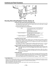
...gain in cases like these settings are: Lr0 dB, Mr9 dB and Hr18 dB. If the AUTO KNEE function is shipped from the camera unit to the VTR unit, viewfinder and video monitor. When the unit is activated in accordance with a high contrast - 16 - When this switch is...be reproduced in the following cases: ÁWhen adjusting the video monitor ÁWhen recording color bar signals The images shot by the camera are output. for automatically adjusting the white balance. When the WHITE BAL switch ® is especially effective for automatically adjusting the black ...
...gain in cases like these settings are: Lr0 dB, Mr9 dB and Hr18 dB. If the AUTO KNEE function is shipped from the camera unit to the VTR unit, viewfinder and video monitor. When the unit is activated in accordance with a high contrast - 16 - When this switch is...be reproduced in the following cases: ÁWhen adjusting the video monitor ÁWhen recording color bar signals The images shot by the camera are output. for automatically adjusting the white balance. When the WHITE BAL switch ® is especially effective for automatically adjusting the black ...

AJSDC915 User Guide
Page 17
... can be monitored. during playback, playback images can be performed simultaneously with the unit's built-in VTR. Even while the VTR is possible to output the sound of audio channels 1 and 2 separately. µ VIDEO OUT connector (BNC) This outputs the video signals (75° termination, ...-pin/12-pin output adaptor AJ-YA900P (option) is mounted on the monitor screen so that the settings can also be checked. ¶ CAM OUT (camera output) connector (BNC) This outputs the composite video signals (75° termination, rated level). While performing settings on the menu, the setting menu can...
... can be monitored. during playback, playback images can be performed simultaneously with the unit's built-in VTR. Even while the VTR is possible to output the sound of audio channels 1 and 2 separately. µ VIDEO OUT connector (BNC) This outputs the video signals (75° termination, ...-pin/12-pin output adaptor AJ-YA900P (option) is mounted on the monitor screen so that the settings can also be checked. ¶ CAM OUT (camera output) connector (BNC) This outputs the composite video signals (75° termination, rated level). While performing settings on the menu, the setting menu can...

AJSDC915 User Guide
Page 18
... cannot be operated longer using "SUPER GAIN" on the MAIN menu 2 of 4 on page 126 for this button is kept depressed, the camera's setting status is the tape protection mode. Compared with the STBY position, less power is released. When it is pressed again, backlight compensation .../STBY (tape protection) switch This selects the power supply status while the VTR recording is allotted to commence after the VTR START button · is pressed again, recording stops. It does not affect the camera's output signals. º SUPER GAIN button (inside sliding cover) This is used when ...
... cannot be operated longer using "SUPER GAIN" on the MAIN menu 2 of 4 on page 126 for this button is kept depressed, the camera's setting status is the tape protection mode. Compared with the STBY position, less power is released. When it is pressed again, backlight compensation .../STBY (tape protection) switch This selects the power supply status while the VTR recording is allotted to commence after the VTR START button · is pressed again, recording stops. It does not affect the camera's output signals. º SUPER GAIN button (inside sliding cover) This is used when ...
AJSDC915 User Guide
Page 20
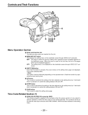
.../OFF switch This displays the setting menu on the viewfinder screen through VIDEO OUT connector. Å SHIFT/ITEM button Each time this connector when the camera section is to be subject to genlock operation or when the time code is to be displayed appears.) OFF: The setting menu is not displayed...
.../OFF switch This displays the setting menu on the viewfinder screen through VIDEO OUT connector. Å SHIFT/ITEM button Each time this connector when the camera section is to be subject to genlock operation or when the time code is to be displayed appears.) OFF: The setting menu is not displayed...

AJSDC915 User Guide
Page 30
... Handling Instructions provided with this unit) - 30 - Lens auto iris adjustment 3. Lens white shading adjustment (with the lens for lens handling. |Note{ The lens and camera adjustments listed below may be necessary depending on the lens to the LENS connector. Lens Clamping Lever Mount Cap 2 Align the indentation at the top...
... Handling Instructions provided with this unit) - 30 - Lens auto iris adjustment 3. Lens white shading adjustment (with the lens for lens handling. |Note{ The lens and camera adjustments listed below may be necessary depending on the lens to the LENS connector. Lens Clamping Lever Mount Cap 2 Align the indentation at the top...
AJSDC915 User Guide
Page 32
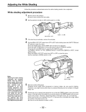
...OFF to SET while holding down the SHIFT/ITEM and UP buttons to SPOT. (Initial setting mode) Return the MENU SET/OFF switch from the camera's picture quality. Flickering occurs easily when fluorescent or mercury lamps, etc. White shading adjustment procedure 1 Mount a lens to allow sufficient time when ...that the ZEBRA pattern covers the entire screen. If the lens iris is between F4 to open the menu. Also, make sure to the camera. Adjusting the White Shading Follow the procedure outlined below when the white shading needs to ON. Set the viewfinder's ZEBRA switch to be re...
...OFF to SET while holding down the SHIFT/ITEM and UP buttons to SPOT. (Initial setting mode) Return the MENU SET/OFF switch from the camera's picture quality. Flickering occurs easily when fluorescent or mercury lamps, etc. White shading adjustment procedure 1 Mount a lens to allow sufficient time when ...that the ZEBRA pattern covers the entire screen. If the lens iris is between F4 to open the menu. Also, make sure to the camera. Adjusting the White Shading Follow the procedure outlined below when the white shading needs to ON. Set the viewfinder's ZEBRA switch to be re...
AJSDC915 User Guide
Page 41
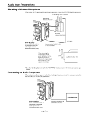
... ÁSee the Handling Instructions for the WX-RA700 wireless receiver for wireless receiver operations. Connecting an Audio Component When using the Panasonic wireless microphone system, mount the WX-RA700 wireless receiver. Connect to the AUDIO IN CH1 or CH2 Connector. When detaching the wireless...connected to REAR [LINE]. - 41 - To the AUDIO OUT Connector WX-RA700 Wireless Receiver WX-R980 Camera Attachment AUDIO IN switch: Set the AUDIO IN switch of the camera attachment (1) and detach the microphone in the upward direction (2). Connect to the AUDIO IN CH1/CH2 Connectors....
... ÁSee the Handling Instructions for the WX-RA700 wireless receiver for wireless receiver operations. Connecting an Audio Component When using the Panasonic wireless microphone system, mount the WX-RA700 wireless receiver. Connect to the AUDIO IN CH1 or CH2 Connector. When detaching the wireless...connected to REAR [LINE]. - 41 - To the AUDIO OUT Connector WX-RA700 Wireless Receiver WX-R980 Camera Attachment AUDIO IN switch: Set the AUDIO IN switch of the camera attachment (1) and detach the microphone in the upward direction (2). Connect to the AUDIO IN CH1/CH2 Connectors....

AJSDC915 User Guide
Page 42
... attachment pin does not return to its original position. Slide the unit forward along the grooves until a clicking sound is heard. Tripod Attachment 2 Mount the camera to a tripod, use an optional tripod attachment. 1 Mount the tripod attachment (SHAN-TM700) onto the tripod. When detaching the tripod attachment Hold down the ...red lever and move the black lever in the direction of the arrow again to return the pin to its original position after the camera has been detached, hold down the red lever and move the black lever in the direction of the arrow. Mounting the Unit to a Tripod...
... attachment pin does not return to its original position. Slide the unit forward along the grooves until a clicking sound is heard. Tripod Attachment 2 Mount the camera to a tripod, use an optional tripod attachment. 1 Mount the tripod attachment (SHAN-TM700) onto the tripod. When detaching the tripod attachment Hold down the ...red lever and move the black lever in the direction of the arrow again to return the pin to its original position after the camera has been detached, hold down the red lever and move the black lever in the direction of the arrow. Mounting the Unit to a Tripod...
AJSDC915 User Guide
Page 46
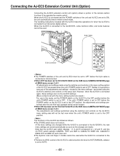
...6-pin cable is connected to OFF. Neither is set to an AQ series digital camera. Connecting the AJ-EC3 Extension Control Unit (Option) Connecting the AJ-EC3 extension control unit (option) allows...EC3 is connected or disconnected. ÁWhen OFF has been set for ECU DATA SAVE on the SUB menu CAMERA SW MODE page of MAIN menu screen 2 of 4 All adjustments and settings made .) Note that the AJ-...EC3 gain switch displays p3, 0 and 9 correspond to L, M and H, and the OUTPUT switch settings CAMERA, TEST and BAR to CAM/AUTO KNEE ON, CAM/AUTO KNEE OFF and BAR for each main unit. ÁThe Synchro...
...6-pin cable is connected to OFF. Neither is set to an AQ series digital camera. Connecting the AJ-EC3 Extension Control Unit (Option) Connecting the AJ-EC3 extension control unit (option) allows...EC3 is connected or disconnected. ÁWhen OFF has been set for ECU DATA SAVE on the SUB menu CAMERA SW MODE page of MAIN menu screen 2 of 4 All adjustments and settings made .) Note that the AJ-...EC3 gain switch displays p3, 0 and 9 correspond to L, M and H, and the OUTPUT switch settings CAMERA, TEST and BAR to CAM/AUTO KNEE ON, CAM/AUTO KNEE OFF and BAR for each main unit. ÁThe Synchro...

AJSDC915 User Guide
Page 47
...) ADDITIONAL DTL (117) SKIN TONE DTL (118) KNEE/LEVEL (119) FLARE/GAMMA (120) CAMERA SETTING (120) VF DISPLAY (121) VF INDICATOR (123) CAMERA ID (124) SHUTTER SPEED (124) SYNCHRO SCAN (125) !LED (125) CAMERA SW MODE (126) SUPER GAIN (127) VTR FUNCTION (128) BATT/TAPE ALARM (130) CARD READ/WRITE (131) CARD R/W SELECT (132...
...) ADDITIONAL DTL (117) SKIN TONE DTL (118) KNEE/LEVEL (119) FLARE/GAMMA (120) CAMERA SETTING (120) VF DISPLAY (121) VF INDICATOR (123) CAMERA ID (124) SHUTTER SPEED (124) SYNCHRO SCAN (125) !LED (125) CAMERA SW MODE (126) SUPER GAIN (127) VTR FUNCTION (128) BATT/TAPE ALARM (130) CARD READ/WRITE (131) CARD R/W SELECT (132...

AJSDC915 User Guide
Page 52
... of 4 now appears. ¢E E E EMA I N MENU 1 / 4 E E E E ROP MA TR I X L OW S E T T I NG M I D SET T I NG H I GH SE T T I NG ADD I T I ONA L DT L SK I N TONE DT L KNEE / LEVEL F L A R E / GAMMA CAMERA SE T T I NG The pages can also be selected using the MENU SET/OFF switch and the SHIFT/ITEM, UP, DOWN and PAGE buttons. tion advances...
... of 4 now appears. ¢E E E EMA I N MENU 1 / 4 E E E E ROP MA TR I X L OW S E T T I NG M I D SET T I NG H I GH SE T T I NG ADD I T I ONA L DT L SK I N TONE DT L KNEE / LEVEL F L A R E / GAMMA CAMERA SE T T I NG The pages can also be selected using the MENU SET/OFF switch and the SHIFT/ITEM, UP, DOWN and PAGE buttons. tion advances...

AJSDC915 User Guide
Page 53
... E E ROP MA TR I X L OW S E T T I NG M I D SET T I NG H I GH SE T T I NG ADD I T I ONA L DT L SK I N TONE DT L KNEE / LEVEL F L A R E / GAMMA CAMERA SE T T I NG SHIFT/ITEM button E E E EMA I N MENU1 / 4 E E E E ¢R O P MA TR I X L OW S E T T I NG M I D SET T I NG H I GH SE T T I NG ADD I T... I ONA L DT L SK I N TONE DT L KNEE / LEVEL F L A R E / GAMMA CAMERA SE T T I NG 2 Press the UP or DOWN button. When this button is advanced by one page (1>2>3>4>1>, etc.). ¢E E E EMA I N MENU 1 / 4 E E E E ROP MA TR I X L OW S E T...
... E E ROP MA TR I X L OW S E T T I NG M I D SET T I NG H I GH SE T T I NG ADD I T I ONA L DT L SK I N TONE DT L KNEE / LEVEL F L A R E / GAMMA CAMERA SE T T I NG SHIFT/ITEM button E E E EMA I N MENU1 / 4 E E E E ¢R O P MA TR I X L OW S E T T I NG M I D SET T I NG H I GH SE T T I NG ADD I T... I ONA L DT L SK I N TONE DT L KNEE / LEVEL F L A R E / GAMMA CAMERA SE T T I NG 2 Press the UP or DOWN button. When this button is advanced by one page (1>2>3>4>1>, etc.). ¢E E E EMA I N MENU 1 / 4 E E E E ROP MA TR I X L OW S E T...


