
English Manual
Page 2
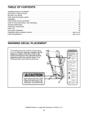
... trademark of ICON IP, Inc. 2 NORDICTRACK is missing or illegible, call the telephone number on the front cover of the warning decals. TABLE OF CONTENTS WARNING DECAL PLACEMENT 2 IMPORTANT PRECAUTIONS 3 BEFORE YOU BEGIN 7 PART IDENTIFICATION CHART 8 ASSEMBLY 9 OPERATION AND ADJUSTMENT 20 HOW TO FOLD AND MOVE THE TREADMILL 29 TROUBLESHOOTING 30 EXERCISE GUIDELINES...
... trademark of ICON IP, Inc. 2 NORDICTRACK is missing or illegible, call the telephone number on the front cover of the warning decals. TABLE OF CONTENTS WARNING DECAL PLACEMENT 2 IMPORTANT PRECAUTIONS 3 BEFORE YOU BEGIN 7 PART IDENTIFICATION CHART 8 ASSEMBLY 9 OPERATION AND ADJUSTMENT 20 HOW TO FOLD AND MOVE THE TREADMILL 29 TROUBLESHOOTING 30 EXERCISE GUIDELINES...
English Manual
Page 4
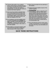
... maintenance and adjustment procedures described in this manual. Inspect and properly tighten all parts of the power switch), and unplug the power cord when the treadmill is not a medical device. Always unplug the power cord immediately after use . 22. The heart rate monitor is holding the frame securely in serious...29.) You must be performed by an authorized service representative. DANGER: 26. Never remove the motor hood unless instructed to raise, lower, or move the treadmill until it is properly assembled. (See ASSEMBLY on page 9, and HOW TO FOLD AND MOVE THE...
... maintenance and adjustment procedures described in this manual. Inspect and properly tighten all parts of the power switch), and unplug the power cord when the treadmill is not a medical device. Always unplug the power cord immediately after use . 22. The heart rate monitor is holding the frame securely in serious...29.) You must be performed by an authorized service representative. DANGER: 26. Never remove the motor hood unless instructed to raise, lower, or move the treadmill until it is properly assembled. (See ASSEMBLY on page 9, and HOW TO FOLD AND MOVE THE...

English Manual
Page 8
...: If a part is not in parentheses below to see if it is preattached. The number following the key number is the quantity used for assembly. Extra parts may be included. #10 Star #10 Washer Washer (5)–-4 (103)–-2 5/16" Star Washer (11)–-10 3/8" Star... 5/16" x 1 3/4" Bolt (6)–-1 5/16" x 2 1/2" Screw (28)–-4 3/8" x 4" Screw (7)–-6 8 The number in the hardware kit, check to identify small parts used for assembly. PART IDENTIFICATION CHART Use the drawings below each drawing is the key number of the part, from the PART LIST near the end of this...
...: If a part is not in parentheses below to see if it is preattached. The number following the key number is the quantity used for assembly. Extra parts may be included. #10 Star #10 Washer Washer (5)–-4 (103)–-2 5/16" Star Washer (11)–-10 3/8" Star... 5/16" x 1 3/4" Bolt (6)–-1 5/16" x 2 1/2" Screw (28)–-4 3/8" x 4" Screw (7)–-6 8 The number in the hardware kit, check to identify small parts used for assembly. PART IDENTIFICATION CHART Use the drawings below each drawing is the key number of the part, from the PART LIST near the end of this...
English Manual
Page 9
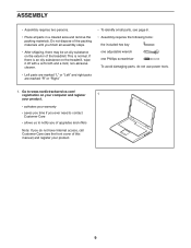
... on your computer and register 1 your product. •• activates your product. 9 ASSEMBLY •• Assembly requires two persons. •• Place all assembly steps. •• After shipping, there may be an oily substance on the exterior of the treadmill. Do not dispose of the packing materials until you do not use power...
... on your computer and register 1 your product. •• activates your product. 9 ASSEMBLY •• Assembly requires two persons. •• Place all assembly steps. •• After shipping, there may be an oily substance on the exterior of the treadmill. Do not dispose of the packing materials until you do not use power...
English Manual
Page 12
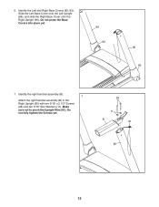
Make sure not to the Right Upright (90) with two 5/16" x 2 1/2" Screws (28) and two 5/16" Star Washers (11). Identify the Left and Right Base Covers (82, 83). 6 Slide the Left Base Cover onto the Left Upright (89), and slide the Right Base Cover onto the Right Upright (90). Identify the right handrail assembly (B). 7 Attach the right handrail assembly (B) to pinch the Upright Wire (81). Do not fully tighten the Screws yet. 28 11 B 81 90 12 Do not press the Base Covers into place yet. 89 82 90 83 7. 6.
Make sure not to the Right Upright (90) with two 5/16" x 2 1/2" Screws (28) and two 5/16" Star Washers (11). Identify the Left and Right Base Covers (82, 83). 6 Slide the Left Base Cover onto the Left Upright (89), and slide the Right Base Cover onto the Right Upright (90). Identify the right handrail assembly (B). 7 Attach the right handrail assembly (B) to pinch the Upright Wire (81). Do not fully tighten the Screws yet. 28 11 B 81 90 12 Do not press the Base Covers into place yet. 89 82 90 83 7. 6.

English Manual
Page 13
do not fully tighten the Screws yet. 28 11 C 89 9. Then, remove the Pulse Crossbar (93). If 9 there are ties securing the Pulse Crossbar (93) to avoid scratching the Console Base. Set the Console Base (64) face down on a soft surface to the Console Base, remove them. Tie 93 64 D Tie 13 Remove and discard the two indicated screws (D). Attach the left handrail assembly (C) to the Left Upright (89) with two 5/16" x 2 1/2" Screws (28) 8 and two 5/16" Star Washers (11); 8.
do not fully tighten the Screws yet. 28 11 C 89 9. Then, remove the Pulse Crossbar (93). If 9 there are ties securing the Pulse Crossbar (93) to avoid scratching the Console Base. Set the Console Base (64) face down on a soft surface to the Console Base, remove them. Tie 93 64 D Tie 13 Remove and discard the two indicated screws (D). Attach the left handrail assembly (C) to the Left Upright (89) with two 5/16" x 2 1/2" Screws (28) 8 and two 5/16" Star Washers (11); 8.

English Manual
Page 15
... THE POWER. The connectors should slide together easily and snap into the Right Upright (90). Make sure not to the console wire. Attach the console assembly to the Console Ground Wire (58) on the Handrails (86) with four 5/16" x 3/4" Screws (4) and four 5/16" Star Washers (11); do not, turn one side... is shown). With the help of a second person, hold the console assembly near the Handrails (86) (only one connector and try again. 12. Connect the ground wire from the Upright Wire. 12 Console...
... THE POWER. The connectors should slide together easily and snap into the Right Upright (90). Make sure not to the console wire. Attach the console assembly to the Console Ground Wire (58) on the Handrails (86) with four 5/16" x 3/4" Screws (4) and four 5/16" Star Washers (11); do not, turn one side... is shown). With the help of a second person, hold the console assembly near the Handrails (86) (only one connector and try again. 12. Connect the ground wire from the Upright Wire. 12 Console...

English Manual
Page 16
... Cover (87) and the Right Outside Upright Cover (96) to overtighten the Screws. 15 Console Assembly 87 C 2 2 89 2 B 90 2 96 16 Check the gaps between the handrail assemblies (B, C) and the console assembly. Make sure not to the Left and Right Uprights (89, 90) with six #8 x ...Start all six Screws, and then tighten them. Firmly tighten the four 5/16" x 3/4" Screws (4). 14 Console Assembly 4 93 1 1 4 1 15. Rotate each Outside Upright Covers needs to the console assembly with two #8 x 3/4" Screws (2). 14. Then, retighten the Screws. Attach the Pulse Crossbar (93) to...
... Cover (87) and the Right Outside Upright Cover (96) to overtighten the Screws. 15 Console Assembly 87 C 2 2 89 2 B 90 2 96 16 Check the gaps between the handrail assemblies (B, C) and the console assembly. Make sure not to the Left and Right Uprights (89, 90) with six #8 x ...Start all six Screws, and then tighten them. Firmly tighten the four 5/16" x 3/4" Screws (4). 14 Console Assembly 4 93 1 1 4 1 15. Rotate each Outside Upright Covers needs to the console assembly with two #8 x 3/4" Screws (2). 14. Then, retighten the Screws. Attach the Pulse Crossbar (93) to...

English Manual
Page 17
... Outside Upright Cover (87) and into the Left and Right Inside Upright Covers (88, not shown) as shown. Tighten a #8 x 3/4" Screw (2) into the bottom of the treadmill with the Right Outside Upright Cover (96) and the Right Inside Upright Cover (95). 104 88 102 17. Repeat the steps above on the other...
... Outside Upright Cover (87) and into the Left and Right Inside Upright Covers (88, not shown) as shown. Tighten a #8 x 3/4" Screw (2) into the bottom of the treadmill with the Right Outside Upright Cover (96) and the Right Inside Upright Cover (95). 104 88 102 17. Repeat the steps above on the other...

English Manual
Page 18
...the Latch Crossbar (38) as shown. Orient the Storage Latch (53) so that the “"This side toward belt”" sticker (D) is facing the treadmill. 18. Attach the lower end of the Storage Latch. 19 Decals Tie Large Barrel 53 12 94 6 18 Raise the Storage Latch (53) to ...the upright position. Have a second person hold the Frame until step 20 is assembled on a smooth surface, the treadmill may roll forward during this step. Then, remove the tie from the treadmill as shown. Raise the Frame (56) to a vertical position. Attach the Latch Crossbar to the bracket...
...the Latch Crossbar (38) as shown. Orient the Storage Latch (53) so that the “"This side toward belt”" sticker (D) is facing the treadmill. 18. Attach the lower end of the Storage Latch. 19 Decals Tie Large Barrel 53 12 94 6 18 Raise the Storage Latch (53) to ...the upright position. Have a second person hold the Frame until step 20 is assembled on a smooth surface, the treadmill may roll forward during this step. Then, remove the tie from the treadmill as shown. Raise the Frame (56) to a vertical position. Attach the Latch Crossbar to the bracket...


