
English Manual
Page 2
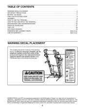
NORDICTRACK and IFIT are trademarks of Google Inc. and other countries and is missing or illegible, call the telephone number on the front cover of Cisco ... trademarks of the warning decals. TABLE OF CONTENTS WARNING DECAL PLACEMENT 2 IMPORTANT PRECAUTIONS 3 BEFORE YOU BEGIN 7 PART IDENTIFICATION CHART 8 ASSEMBLY 9 HOW TO USE THE TREADMILL 19 HOW TO FOLD AND MOVE THE TREADMILL 33 MAINTENANCE AND TROUBLESHOOTING 34 EXERCISE GUIDELINES 37 PART LIST 38 EXPLODED DRAWING 40 ORDERING REPLACEMENT PARTS Back Cover LIMITED...
NORDICTRACK and IFIT are trademarks of Google Inc. and other countries and is missing or illegible, call the telephone number on the front cover of Cisco ... trademarks of the warning decals. TABLE OF CONTENTS WARNING DECAL PLACEMENT 2 IMPORTANT PRECAUTIONS 3 BEFORE YOU BEGIN 7 PART IDENTIFICATION CHART 8 ASSEMBLY 9 HOW TO USE THE TREADMILL 19 HOW TO FOLD AND MOVE THE TREADMILL 33 MAINTENANCE AND TROUBLESHOOTING 34 EXERCISE GUIDELINES 37 PART LIST 38 EXPLODED DRAWING 40 ORDERING REPLACEMENT PARTS Back Cover LIMITED...
English Manual
Page 4
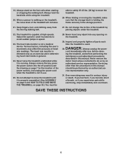
...the power switch), and unplug the power cord when the treadmill is properly assembled. (See ASSEMBLY on page 9 and HOW TO FOLD AND MOVE THE TREADMILL on page 7 for the location of the treadmill will increase. Never leave the treadmill unattended while it is not in this manual should be 28.... DANGER: 30. 19. ing the treadmill, and before performing the ...
...the power switch), and unplug the power cord when the treadmill is properly assembled. (See ASSEMBLY on page 9 and HOW TO FOLD AND MOVE THE TREADMILL on page 7 for the location of the treadmill will increase. Never leave the treadmill unattended while it is not in this manual should be 28.... DANGER: 30. 19. ing the treadmill, and before performing the ...
English Manual
Page 8
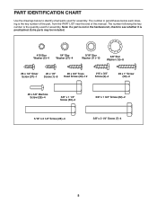
The number in the hardware kit, check to identify small parts used for assembly. PART IDENTIFICATION CHART Use the drawings below each drawing is preattached. Note: If a part is not in parentheses below to see whether it is the ... x 3/4" Screw (9)-4 #8 x 1" Screw (50)-2 #8 x 5/8" Machine Screw (26)-4 3/8" x 1 1/4" Screw (63)-2 3/8" x 1 3/4" Screw (62)-2 5/16" x 2 1/2" Screw (28)-4 3/8" x 2 1/4" Screw (7)-4 8 The number following the key number is the quantity used for assembly.
The number in the hardware kit, check to identify small parts used for assembly. PART IDENTIFICATION CHART Use the drawings below each drawing is preattached. Note: If a part is not in parentheses below to see whether it is the ... x 3/4" Screw (9)-4 #8 x 1" Screw (50)-2 #8 x 5/8" Machine Screw (26)-4 3/8" x 1 1/4" Screw (63)-2 3/8" x 1 3/4" Screw (62)-2 5/16" x 2 1/2" Screw (28)-4 3/8" x 2 1/4" Screw (7)-4 8 The number following the key number is the quantity used for assembly.
English Manual
Page 9
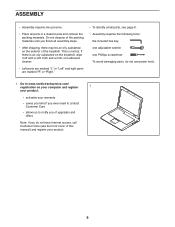
...is an oily substance on the treadmill, wipe it off with a soft cloth and a mild, non-abrasive cleaner. • Left parts are marked "L" or "Left" and right parts are marked "R" or "Right." • To identify small parts, see page 8. • Assembly requires the following tools: the ...dispose of the packing materials until you finish all parts in a cleared area and remove the packing materials. ASSEMBLY • Assembly requires two persons. • Place all assembly steps. • After shipping, there may be an oily substance on the exterior of upgrades and offers Note: If...
...is an oily substance on the treadmill, wipe it off with a soft cloth and a mild, non-abrasive cleaner. • Left parts are marked "L" or "Left" and right parts are marked "R" or "Right." • To identify small parts, see page 8. • Assembly requires the following tools: the ...dispose of the packing materials until you finish all parts in a cleared area and remove the packing materials. ASSEMBLY • Assembly requires two persons. • Place all assembly steps. • After shipping, there may be an oily substance on the exterior of upgrades and offers Note: If...
English Manual
Page 13
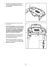
.... Next, insert the two pulse wires (G, H) into place. Attach the console assembly (F) with the four 1/4" x 1/2" Screws (4) that you set the console assembly onto the brackets on a soft surface to avoid scratching the console assembly. See the inset drawing. 8. Set the console assembly (F) face down on the Handrails (86); Remove and save the four 1/4" x 1/2" Screws...
.... Next, insert the two pulse wires (G, H) into place. Attach the console assembly (F) with the four 1/4" x 1/2" Screws (4) that you set the console assembly onto the brackets on a soft surface to avoid scratching the console assembly. See the inset drawing. 8. Set the console assembly (F) face down on the Handrails (86); Remove and save the four 1/4" x 1/2" Screws...
English Manual
Page 14
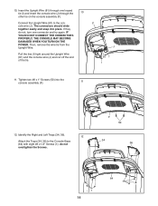
... Wire. do not, turn one looped tie (I) and insert the console wire (J) through the 10 other tie on the console assembly (F). The connectors should slide together easily and snap into the console assembly (F). 11 12. Tighten two #8 x 1" Screws (50) into place. F J 81 I I ) tight around the Upright Wire (81) and the console wire...
... Wire. do not, turn one looped tie (I) and insert the console wire (J) through the 10 other tie on the console assembly (F). The connectors should slide together easily and snap into the console assembly (F). 11 12. Tighten two #8 x 1" Screws (50) into place. F J 81 I I ) tight around the Upright Wire (81) and the console wire...
English Manual
Page 16
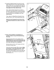
Note: If the treadmill is facing the treadmill. do not overtighten the Truss Head Screws. Attach the Latch Crossbar to the ... 23 85 23 F 92 23 86 23 84 16. Make sure that the "This side toward belt" sticker (K) is assembled on the right Handrail (86). 15. Remove the two 5/16" x 3/4" Screws (31) from the Latch Crossbar (38...8 x 3/4" Truss Head Screws (23). Set the Right Handrail Cover on a smooth surface, it rests against the console assembly (F). Have a second person hold the Frame until it may roll forward during this step. IMPORTANT: Do not raise the...
Note: If the treadmill is facing the treadmill. do not overtighten the Truss Head Screws. Attach the Latch Crossbar to the ... 23 85 23 F 92 23 86 23 84 16. Make sure that the "This side toward belt" sticker (K) is assembled on the right Handrail (86). 15. Remove the two 5/16" x 3/4" Screws (31) from the Latch Crossbar (38...8 x 3/4" Truss Head Screws (23). Set the Right Handrail Cover on a smooth surface, it rests against the console assembly (F). Have a second person hold the Frame until it may roll forward during this step. IMPORTANT: Do not raise the...
English Manual
Page 18
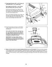
... the Right Upright (90). Make sure that all parts are sheets of direct sunlight. To protect the floor or carpet, place a mat under the treadmill. Next, tighten the two 3/8" x 1 3/4" Screws (62); the Wheels (97) must turn freely. Do not overtighten the Machine Screws. Do not place ...any other electronic device or object in the console assembly (F). one of the hex keys is designed for use the treadmill. Press the two tabs (not shown) on the treadmill decals, remove the plastic. IMPORTANT: The Tablet Holder (105) is used to the console...
... the Right Upright (90). Make sure that all parts are sheets of direct sunlight. To protect the floor or carpet, place a mat under the treadmill. Next, tighten the two 3/8" x 1 3/4" Screws (62); the Wheels (97) must turn freely. Do not overtighten the Machine Screws. Do not place ...any other electronic device or object in the console assembly (F). one of the hex keys is designed for use the treadmill. Press the two tabs (not shown) on the treadmill decals, remove the plastic. IMPORTANT: The Tablet Holder (105) is used to the console...


