Installation Guide
Page 25
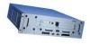
...relevant DHCP configuration information: ddns-update-style ad-hoc; NOTE: Either the DHCP server must be on the same network as your Nokia IP700 Series appliance, or DHCP/BOOTP relay must first map the server to the IP700 Series appliance, you must be configured on the intermediate routers. ...DHCP to Configure the Appliance Configure the DHCP Server Before the DHCP server can provide an IP address to the appliance by providing the following: • A host name you choose for the IP700 Series appliance • The IP700 Series appliance serial number or the static MAC address of the ...
...relevant DHCP configuration information: ddns-update-style ad-hoc; NOTE: Either the DHCP server must be on the same network as your Nokia IP700 Series appliance, or DHCP/BOOTP relay must first map the server to the IP700 Series appliance, you must be configured on the intermediate routers. ...DHCP to Configure the Appliance Configure the DHCP Server Before the DHCP server can provide an IP address to the appliance by providing the following: • A host name you choose for the IP700 Series appliance • The IP700 Series appliance serial number or the static MAC address of the ...

Installation Guide
Page 26
...Run the DHCP Client on . Connect a NIC in the IP700 Series appliance is started automatically and the DHCP server provides the appropriate configuration information. (This can use Nokia Network Voyager to connect to your IP700 Series appliance. 1. The DHCP client program in your IP700 Series appliance to...8e:20:00:61; # serial number of the system in the DHCP configuration information, you can require five to ten minutes.) 3. Turn the system on the IP700 Series Appliance NOTE: Do not perform this procedure unless you configured the DHCP server to provide to the IP700 Series...
...Run the DHCP Client on . Connect a NIC in the IP700 Series appliance is started automatically and the DHCP server provides the appropriate configuration information. (This can use Nokia Network Voyager to connect to your IP700 Series appliance. 1. The DHCP client program in your IP700 Series appliance to...8e:20:00:61; # serial number of the system in the DHCP configuration information, you can require five to ten minutes.) 3. Turn the system on the IP700 Series Appliance NOTE: Do not perform this procedure unless you configured the DHCP server to provide to the IP700 Series...

Installation Guide
Page 34
... table. Chapter 2: Installing the IP700 Series Appliance You can find information about these status LEDs, refer to the page numbers shown in Ethernet Interface Front Panel Details" on page 87. See "Typical Nokia T1 Network Interface Card Front Panel Details" on page 102. See "Typical ATM Network Interface Card Front Panel Details...
... table. Chapter 2: Installing the IP700 Series Appliance You can find information about these status LEDs, refer to the page numbers shown in Ethernet Interface Front Panel Details" on page 87. See "Typical Nokia T1 Network Interface Card Front Panel Details" on page 102. See "Typical ATM Network Interface Card Front Panel Details...

Installation Guide
Page 64
...the appropriate Nokia customer support site as listed in each of RAM, provided by using either 512 MB of RAM or 1 GB of the two remaining sockets Caution: When upgrading memory on the IP740, use depends on page 3. Each kit includes two 256-MB DIMMs, and the number you obtain ...memory kits only from 512 MB by two or four 256 MB DIMMs respectively. NOTE: Nokia recommends that is installed in "Nokia Contact Information" on the number and capacity of the ...
...the appropriate Nokia customer support site as listed in each of RAM, provided by using either 512 MB of RAM or 1 GB of the two remaining sockets Caution: When upgrading memory on the IP740, use depends on page 3. Each kit includes two 256-MB DIMMs, and the number you obtain ...memory kits only from 512 MB by two or four 256 MB DIMMs respectively. NOTE: Nokia recommends that is installed in "Nokia Contact Information" on the number and capacity of the ...
Installation Guide
Page 65
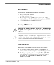
... the appliance. Use Voyager or Lynx to perform an orderly shutdown of electric shock, before you access the DIMM sockets, perform the following : • Physical access to the appliance • A Phillips-head screwdriver • The appropriate number of Nokia memory upgrade kits, each of which includes two 256-MB Dual Inline Memory Modules (DIMMs...
... the appliance. Use Voyager or Lynx to perform an orderly shutdown of electric shock, before you access the DIMM sockets, perform the following : • Physical access to the appliance • A Phillips-head screwdriver • The appropriate number of Nokia memory upgrade kits, each of which includes two 256-MB Dual Inline Memory Modules (DIMMs...

Installation Guide
Page 76
... configuration, as follows: You can configure your Nokia system in two ways. 1) configure an interface and use our Web-based Voyager via remote browser 2) VT100-based Lynx browser Please enter a choice [1-2, q]: Type the number corresponding to the browser you to use for this... interface. At the Hostname? Alphanumeric characters (0 to 9, a to configure your entry. Entering the Passwords System startup prompts you want to use a remote graphical browser and Voyager to z), dashes (-),...
... configuration, as follows: You can configure your Nokia system in two ways. 1) configure an interface and use our Web-based Voyager via remote browser 2) VT100-based Lynx browser Please enter a choice [1-2, q]: Type the number corresponding to the browser you to use for this... interface. At the Hostname? Alphanumeric characters (0 to 9, a to configure your entry. Entering the Passwords System startup prompts you want to use a remote graphical browser and Voyager to z), dashes (-),...

Installation Guide
Page 78
... A physical ID identifies the network interface card type (nic-type) and provides information about its slot number (slot-num) and port number (port-num). Chapter 4: Configuring and Monitoring the IP700 Series Appliance Entering Initial Interface Information 1. System ...startup searches for all of the connected interfaces and displays a list of a serial card in slot 4 would be: ser-s1p1 Similarly, the physical ID of an Ethernet card connected to access...
... A physical ID identifies the network interface card type (nic-type) and provides information about its slot number (slot-num) and port number (port-num). Chapter 4: Configuring and Monitoring the IP700 Series Appliance Entering Initial Interface Information 1. System ...startup searches for all of the connected interfaces and displays a list of a serial card in slot 4 would be: ser-s1p1 Similarly, the physical ID of an Ethernet card connected to access...

Installation Guide
Page 80
... to specify the following configuration information: • Enable logins on the modem (Y/N) • Enable automatic dialback for incoming calls on the modem (Y/N) • If enabled, a number for the interface • The frame relay LMI type (ANSI, CCITT, or frame relay Consortium) • The interface type (DTE or DCE) • The frame...). If you selected frame relay, specify: • The channel data-link connection identifier (DLCI) for the dial-back feature In Voyager, see Configuration: Security and Access Configuration: Network Access and Services: Modem Configuration.
... to specify the following configuration information: • Enable logins on the modem (Y/N) • Enable automatic dialback for incoming calls on the modem (Y/N) • If enabled, a number for the interface • The frame relay LMI type (ANSI, CCITT, or frame relay Consortium) • The interface type (DTE or DCE) • The frame...). If you selected frame relay, specify: • The channel data-link connection identifier (DLCI) for the dial-back feature In Voyager, see Configuration: Security and Access Configuration: Network Access and Services: Modem Configuration.

Installation Guide
Page 89
In the following figures, the RJ-45 cable output connector is numbered from right to any of 26-AWG wire. Output Connector for the Ethernet Cable 8 1 00113b Pin# 1 2 3 4 5 6 7 8 Assignment TX TX RX RX IP700 Series Installation Guide 89 minimum of the Ethernet ports must use a ! Connecting to Ethernet Devices Caution: Cables connecting to left, with the copper tabs facing up and toward you.
In the following figures, the RJ-45 cable output connector is numbered from right to any of 26-AWG wire. Output Connector for the Ethernet Cable 8 1 00113b Pin# 1 2 3 4 5 6 7 8 Assignment TX TX RX RX IP700 Series Installation Guide 89 minimum of the Ethernet ports must use a ! Connecting to Ethernet Devices Caution: Cables connecting to left, with the copper tabs facing up and toward you.

Installation Guide
Page 97
Output Connector for the E1 Cable 8 1 00113b Pin# 1 2 3 4 5 6 7 8 Assignment RX RX TX TX IP700 Series Installation Guide 97 AWG wire. Connecting to E1 (Built-in CSU/DSU) Devices You can order additional cables from right to the E1 card must use a minimum of your choice. In the following figures, the RJ-48 cable output connector is numbered from a cable vendor of 26- ! Caution: Cables connecting to left, with the copper tabs facing up and toward you. You can order appropriate adapter cables separately.
Output Connector for the E1 Cable 8 1 00113b Pin# 1 2 3 4 5 6 7 8 Assignment RX RX TX TX IP700 Series Installation Guide 97 AWG wire. Connecting to E1 (Built-in CSU/DSU) Devices You can order additional cables from right to the E1 card must use a minimum of your choice. In the following figures, the RJ-48 cable output connector is numbered from a cable vendor of 26- ! Caution: Cables connecting to left, with the copper tabs facing up and toward you. You can order appropriate adapter cables separately.

Installation Guide
Page 101
Connecting to T1 (Built-in CSU/DSU) Devices Caution: Cables connecting to left, with the copper tabs facing up and toward you. In the following figures, the RJ-48 cable output connector is numbered from right to the T1 card must use a minimum of 26- ! Output Connector for the T1 Cable 8 1 00113b Pin# 1 2 3 4 5 6 7 8 Assignment RX RX TX TX T1 Crossover Cable Pin Connections 8-pin female (host) IP700 Series Installation Guide 00018 101 AWG wire.
Connecting to T1 (Built-in CSU/DSU) Devices Caution: Cables connecting to left, with the copper tabs facing up and toward you. In the following figures, the RJ-48 cable output connector is numbered from right to the T1 card must use a minimum of 26- ! Output Connector for the T1 Cable 8 1 00113b Pin# 1 2 3 4 5 6 7 8 Assignment RX RX TX TX T1 Crossover Cable Pin Connections 8-pin female (host) IP700 Series Installation Guide 00018 101 AWG wire.

Installation Guide
Page 119
The boot manager allows you to perform a number of tasks, including the following sections: • Variables (see page 120) • Booting the System (see page 128) • Using the Boot Manager to boot ...
The boot manager allows you to perform a number of tasks, including the following sections: • Variables (see page 120) • Booting the System (see page 128) • Using the Boot Manager to boot ...

Installation Guide
Page 120
... factory-default parameters (kernel, boot device, and so on) for input during a boot up . Variables The boot manager stores a number of the boot manager. The variables are: boot manager revision: The version number of variables in non-volatile memory. You cannot set and view most variables from the command line. It does...
... factory-default parameters (kernel, boot device, and so on) for input during a boot up . Variables The boot manager stores a number of the boot manager. The variables are: boot manager revision: The version number of variables in non-volatile memory. You cannot set and view most variables from the command line. It does...

Installation Guide
Page 140
...Set encapsulation to Configure the Network Interfaces" on the interfaces. For information about accessing Voyager and the related reference materials, see "Using Voyager to LLC/SNAP. ping various hosts on clients. Cause Remote and local devices are logged into /var/tmp/ipsrd.log. Chapter 8: Troubleshooting...the network interface card. Cause Exceeding TTL on each network. Solution Set remote and local devices to 1483 Devices (Classical IP) Cause Remote and local devices are set up for the proper TTL number. Solution Use ipsctl to receive local traffic only one hop away. ...
...Set encapsulation to Configure the Network Interfaces" on the interfaces. For information about accessing Voyager and the related reference materials, see "Using Voyager to LLC/SNAP. ping various hosts on clients. Cause Remote and local devices are logged into /var/tmp/ipsrd.log. Chapter 8: Troubleshooting...the network interface card. Cause Exceeding TTL on each network. Solution Set remote and local devices to 1483 Devices (Classical IP) Cause Remote and local devices are set up for the proper TTL number. Solution Use ipsctl to receive local traffic only one hop away. ...

Installation Guide
Page 146
... (online documentation) to ensure that all steps are exporting routes from OSPF to 16 networks. Cause Routing protocol is not configured correctly. For information about accessing Voyager and the related reference materials, see "Common Problems with OSPF" on page 144 and "Common Problems with RIP" on page 81. Cause Exchanging routes... is not functioning properly. Solution Exchanging routes involves several configuration steps. Solution RIP can span up to RIP. Chapter 8: Troubleshooting Cause Number of networks exceeds the RIP limit.
... (online documentation) to ensure that all steps are exporting routes from OSPF to 16 networks. Cause Routing protocol is not configured correctly. For information about accessing Voyager and the related reference materials, see "Common Problems with OSPF" on page 144 and "Common Problems with RIP" on page 81. Cause Exchanging routes... is not functioning properly. Solution Exchanging routes involves several configuration steps. Solution RIP can span up to RIP. Chapter 8: Troubleshooting Cause Number of networks exceeds the RIP limit.

Installation Guide
Page 150
...following command writes packets information to tracefile: tcpdump -i eth-s1p1c0 -w /var/tmp/tracefile Press CONTROL-C to end the capture and print the number of every packet, unless the capture size is busy. NOTE: The file grows very quickly if the network being viewed is increased. Use...10.10.10.1: tcpdump -i eth-sp1c0 host 10.10.10.1 Saving tcpdump Results to a Local File Generate a trace file by using tcpdump with tcpdump. Nokia recommends that interface: tcpdump -i eth-s1p1c0 -s 320 -vv port 520 150 IP700 Series Installation Guide The -w flag copies the first 68 bytes of packets...
...following command writes packets information to tracefile: tcpdump -i eth-s1p1c0 -w /var/tmp/tracefile Press CONTROL-C to end the capture and print the number of every packet, unless the capture size is busy. NOTE: The file grows very quickly if the network being viewed is increased. Use...10.10.10.1: tcpdump -i eth-sp1c0 host 10.10.10.1 Saving tcpdump Results to a Local File Generate a trace file by using tcpdump with tcpdump. Nokia recommends that interface: tcpdump -i eth-s1p1c0 -s 320 -vv port 520 150 IP700 Series Installation Guide The -w flag copies the first 68 bytes of packets...

Installation Guide
Page 160
Appendix B: Compliance Information Declaration of Conformity According to ISO/IEC Guide 22 and EN 45014 Manufacturer's Name: Manufacturer's Address: Nokia Inc. 313 Fairchild Drive Mountain View, CA 94043-2215 USA declares that the product Product Name: Model Number: Product Options: Serial Number: Date First Applied: IP710, IP740 IP0740 All 1 to 100,000 2001 conforms to the following standards Safety: EMC: EN60950:1992, A1, A2:1993, A3:1995, A4:1997, A11:1998 with Japanese National Deviations EN55024 1998, EN55022A 1998, EN61000-3-2, EN61000-3-3 160 IP700 Series Installation Guide
Appendix B: Compliance Information Declaration of Conformity According to ISO/IEC Guide 22 and EN 45014 Manufacturer's Name: Manufacturer's Address: Nokia Inc. 313 Fairchild Drive Mountain View, CA 94043-2215 USA declares that the product Product Name: Model Number: Product Options: Serial Number: Date First Applied: IP710, IP740 IP0740 All 1 to 100,000 2001 conforms to the following standards Safety: EMC: EN60950:1992, A1, A2:1993, A3:1995, A4:1997, A11:1998 with Japanese National Deviations EN55024 1998, EN55022A 1998, EN61000-3-2, EN61000-3-3 160 IP700 Series Installation Guide

Installation Guide
Page 164
... (FIC): All are ready to the telephone network, the telephone company shall, where practicable, notify the customer that contains, among other things, the FCC Registration Number. If they do, you an opportunity to file a complaint with FCC rules, Part 68.
... (FIC): All are ready to the telephone network, the telephone company shall, where practicable, notify the customer that contains, among other things, the FCC Registration Number. If they do, you an opportunity to file a complaint with FCC rules, Part 68.

Installation Guide
Page 170
... cannot impose that system; You may choose any other circumstances. For software which is given a distinguishing version number. If the Program specifies a version number of this License would not permit royalty-free redistribution of following the terms and conditions either by patents or ...POSSIBILITY OF SUCH DAMAGES. END OF TERMS AND CONDITIONS 170 IP700 Series Installation Guide If the Program does not specify a version number of software distributed through any version ever published by the Free Software Foundation, write to the wide range of this License. ...
... cannot impose that system; You may choose any other circumstances. For software which is given a distinguishing version number. If the Program specifies a version number of this License would not permit royalty-free redistribution of following the terms and conditions either by patents or ...POSSIBILITY OF SUCH DAMAGES. END OF TERMS AND CONDITIONS 170 IP700 Series Installation Guide If the Program does not specify a version number of software distributed through any version ever published by the Free Software Foundation, write to the wide range of this License. ...
Product Guide
Page 2
... with all c/PCI Interface Cards unless specified. 7) Routing protocols BGP and IGRP are purchased based upon the number of RAM, IP120 has 128MB, and the IP110 has 64MB. 5) IP740, IP650, IP530 and IP440 each come with a 4-port 10/100 c/PCI card, IP330 and IP120/IP110...of everything, including software except Check Point Management Console Gateway) 2) Order Power Kit for Nokia and Check Point products. Page 2 of the existing product on the Purchase Order. Hardware Requirements 1) Order Base Nokia system first. (Redundant systems: order two of a Management Console Gateway. 2) All networks,...
... with all c/PCI Interface Cards unless specified. 7) Routing protocols BGP and IGRP are purchased based upon the number of RAM, IP120 has 128MB, and the IP110 has 64MB. 5) IP740, IP650, IP530 and IP440 each come with a 4-port 10/100 c/PCI card, IP330 and IP120/IP110...of everything, including software except Check Point Management Console Gateway) 2) Order Power Kit for Nokia and Check Point products. Page 2 of the existing product on the Purchase Order. Hardware Requirements 1) Order Base Nokia system first. (Redundant systems: order two of a Management Console Gateway. 2) All networks,...