
Installation Guide
Page 6
Contents Monitoring and Replacing a Power Supply 61 Upgrading the Memory 64 CHAPTER 4 Configuring and Monitoring the IP700 Series Appliance 75 Entering the Hostname 76 Entering the Passwords 76 Entering the Browser Type 76 Entering... (Built-in CSU/DSU) Devices . . . . 99 Connecting to ATM Devices 102 Connecting to Gigabit Ethernet Devices 104 Connecting to a Modem 107 CHAPTER 6 Installing the Nokia Encryption Accelerator Card 109 Installing the Encryption Accelerator Card 110 Enabling the Encryption Accelerator Card 117 CHAPTER 7 Using the Boot Manager 119 Variables 120 Booting...
Contents Monitoring and Replacing a Power Supply 61 Upgrading the Memory 64 CHAPTER 4 Configuring and Monitoring the IP700 Series Appliance 75 Entering the Hostname 76 Entering the Passwords 76 Entering the Browser Type 76 Entering... (Built-in CSU/DSU) Devices . . . . 99 Connecting to ATM Devices 102 Connecting to Gigabit Ethernet Devices 104 Connecting to a Modem 107 CHAPTER 6 Installing the Nokia Encryption Accelerator Card 109 Installing the Encryption Accelerator Card 110 Enabling the Encryption Accelerator Card 117 CHAPTER 7 Using the Boot Manager 119 Variables 120 Booting...

Installation Guide
Page 35
... Drive Unit (see page 53) • Replacing the Fan Tray (see page 59) • Monitoring and Replacing a Power Supply (see page 61) • Upgrading the Memory (see page 64) IP700 Series Installation Guide 35 However, if you need to add or replace a NIC, this chapter provides instructions on how to do...
... Drive Unit (see page 53) • Replacing the Fan Tray (see page 59) • Monitoring and Replacing a Power Supply (see page 61) • Upgrading the Memory (see page 64) IP700 Series Installation Guide 35 However, if you need to add or replace a NIC, this chapter provides instructions on how to do...

Installation Guide
Page 64
... is installed in "Nokia Contact Information" on page 3. Each kit includes two 256-MB DIMMs, and the number you obtain memory kits only from 512 MB by two or four 256 MB DIMMs respectively. The IP700 Series appliance base system contains four dual inline memory module (DIMM) sockets. The IP740 appliance base system ships...
... is installed in "Nokia Contact Information" on page 3. Each kit includes two 256-MB DIMMs, and the number you obtain memory kits only from 512 MB by two or four 256 MB DIMMs respectively. The IP700 Series appliance base system contains four dual inline memory module (DIMM) sockets. The IP740 appliance base system ships...
Installation Guide
Page 65
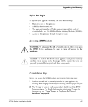
...is currently installed in your appliance memory, you touch these components. Preinstallation Steps Before you access the DIMM sockets, perform the following : • Physical access to the appliance • A Phillips-head screwdriver • The appropriate number of Nokia memory upgrade kits, each of which ...includes two 256-MB Dual Inline Memory Modules (DIMMs) • Access to the appliance through Voyager or Lynx Accessing DIMM Sockets WARNING: To minimize the risk of the IP700 ...
...is currently installed in your appliance memory, you touch these components. Preinstallation Steps Before you access the DIMM sockets, perform the following : • Physical access to the appliance • A Phillips-head screwdriver • The appropriate number of Nokia memory upgrade kits, each of which ...includes two 256-MB Dual Inline Memory Modules (DIMMs) • Access to the appliance through Voyager or Lynx Accessing DIMM Sockets WARNING: To minimize the risk of the IP700 ...

Installation Guide
Page 67
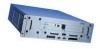
Use a screwdriver to unscrew the two screws that secure each power supply to disengage the motherboard chassis assembly from its connectors and prevents the front panel from being damaged as the chassis assembly is pulled out). a. Remove the two power supplies as follows (removing the power supplies allows you to the chassis. 00099 IP700 Series Installation Guide 67 Upgrading the Memory Accessing and Removing the Existing DIMMs To install the memory upgrade kit, use the following procedure. 1.
Use a screwdriver to unscrew the two screws that secure each power supply to disengage the motherboard chassis assembly from its connectors and prevents the front panel from being damaged as the chassis assembly is pulled out). a. Remove the two power supplies as follows (removing the power supplies allows you to the chassis. 00099 IP700 Series Installation Guide 67 Upgrading the Memory Accessing and Removing the Existing DIMMs To install the memory upgrade kit, use the following procedure. 1.

Installation Guide
Page 69
Upgrading the Memory 3. Slide the chassis assembly forward to expose the motherboard components, as the following figure shows. 00171 IP700 Series Installation Guide 69
Upgrading the Memory 3. Slide the chassis assembly forward to expose the motherboard components, as the following figure shows. 00171 IP700 Series Installation Guide 69

Installation Guide
Page 70
DIMM Socket Locations Front of Motherboard Installing the New DIMMs in the IP700 Series Appliance You can upgrade the memory of the IP700 mother board, as you look at the appliance from the front, as the following figure shows. Chapter 3: Installing, Monitoring, and Replacing Components The DIMM sockets are located at the right of the IP700 Series appliance to 1 GB by inserting two additional 256 MB DIMMs. 70 IP700 Series Installation Guide
DIMM Socket Locations Front of Motherboard Installing the New DIMMs in the IP700 Series Appliance You can upgrade the memory of the IP700 mother board, as you look at the appliance from the front, as the following figure shows. Chapter 3: Installing, Monitoring, and Replacing Components The DIMM sockets are located at the right of the IP700 Series appliance to 1 GB by inserting two additional 256 MB DIMMs. 70 IP700 Series Installation Guide
Installation Guide
Page 71
... opposite ends of the DIMM alternately to the front of the four sockets. This requires two memory kits. 1. Upgrading the Memory For each DIMM you remove from the contact pins. 00121b NOTE: IP700 Series appliances use interleaved memory and work in adjacent DIMM sockets. Therefore, two DIMMs would not be installed in pairs...
... opposite ends of the DIMM alternately to the front of the four sockets. This requires two memory kits. 1. Upgrading the Memory For each DIMM you remove from the contact pins. 00121b NOTE: IP700 Series appliances use interleaved memory and work in adjacent DIMM sockets. Therefore, two DIMMs would not be installed in pairs...

Installation Guide
Page 73
Upgrading the Memory 2. Replace the retaining screws and screw them into place. 00087 3. Turn on the power. IP700 Series Installation Guide 73 Reattach the power cords. 5. You can verify this from the Voyager or Lynx interface. Slide the two power supplies into place. 4. The appliance automatically recognizes the new memory configuration.
Upgrading the Memory 2. Replace the retaining screws and screw them into place. 00087 3. Turn on the power. IP700 Series Installation Guide 73 Reattach the power cords. 5. You can verify this from the Voyager or Lynx interface. Slide the two power supplies into place. 4. The appliance automatically recognizes the new memory configuration.

Installation Guide
Page 120
... commands. Factory default: five seconds. 120 IP700 Series Installation Guide The variables are: boot manager revision: The version number of variables in non-volatile memory. Chapter 7: Using the Boot Manager • Installing Boot Manager (see page 131) • Upgrading Boot Manager (see page 132) When you ...the boot process. Factory default: yes. If input is set to yes. The boot manager maintains the default values of time, in flash memory. otherwise, it proceeds with the boot up when autoboot is received, the boot manager goes to bypass the boot manager prompt after a five...
... commands. Factory default: five seconds. 120 IP700 Series Installation Guide The variables are: boot manager revision: The version number of variables in non-volatile memory. Chapter 7: Using the Boot Manager • Installing Boot Manager (see page 131) • Upgrading Boot Manager (see page 132) When you ...the boot process. Factory default: yes. If input is set to yes. The boot manager maintains the default values of time, in flash memory. otherwise, it proceeds with the boot up when autoboot is received, the boot manager goes to bypass the boot manager prompt after a five...

Installation Guide
Page 121
boot-flags: The string of the file to use as possible in the boot manager nonvolatile memory. Enters the kernel debugger as soon as the operating system kernel. The command has the following table lists possible boot flags. The following form... Series Installation Guide 121 Verbose during device probing and thereafter. Do not identify the flash disk as insecure, the root password must be entered to access the manager. -v Verbose mode. This command is -x always needed for the IP700 Series appliances and is marked as wd0. Factory default: -x. boot-device:...
boot-flags: The string of the file to use as possible in the boot manager nonvolatile memory. Enters the kernel debugger as soon as the operating system kernel. The command has the following table lists possible boot flags. The following form... Series Installation Guide 121 Verbose during device probing and thereafter. Do not identify the flash disk as insecure, the root password must be entered to access the manager. -v Verbose mode. This command is -x always needed for the IP700 Series appliances and is marked as wd0. Factory default: -x. boot-device:...

Installation Guide
Page 122
... to wd3 Alias 3: net1 aliased to eth-s3p1 Alias 4: net2 aliased to view the values of the aliases currently stored in the boot manager nonvolatile memory. Chapter 7: Using the Boot Manager For example: BOOTMGR[93]> printenv Bootmgr Revision: 3.2.1,base kernel= 3.2.1-fcs1 11.24.1999-102644 autoboot: YES bootwait: 5 boot-file: /image...
... to wd3 Alias 3: net1 aliased to eth-s3p1 Alias 4: net2 aliased to view the values of the aliases currently stored in the boot manager nonvolatile memory. Chapter 7: Using the Boot Manager For example: BOOTMGR[93]> printenv Bootmgr Revision: 3.2.1,base kernel= 3.2.1-fcs1 11.24.1999-102644 autoboot: YES bootwait: 5 boot-file: /image...

Installation Guide
Page 123
..., and so forth. The command has the following form: sysinfo For example: BOOTMGR[1]> sysinfo CPU 0: 1000 MHz Pentium-III w ATC Memory: 536870912 (512M bytes) Disk Devices: IO port 0x1f0 wdc0: unit 1 (wd0): 20576MB (40188960 sectors), 2501 cyls, 255 heads, 63 S/T, 512 B/S IO port 0x1f0 wdc0: unit 0 (...
..., and so forth. The command has the following form: sysinfo For example: BOOTMGR[1]> sysinfo CPU 0: 1000 MHz Pentium-III w ATC Memory: 536870912 (512M bytes) Disk Devices: IO port 0x1f0 wdc0: unit 1 (wd0): 20576MB (40188960 sectors), 2501 cyls, 255 heads, 63 S/T, 512 B/S IO port 0x1f0 wdc0: unit 0 (...

Installation Guide
Page 128
...-flags Default wd0 (the hard disk) /image/current/kernel -x 128 IP700 Series Installation Guide For a list of the command. It first searches its non-volatile memory to see the boot flag table in "Variables" on page 120. It allows you boot up and boot-file is the storage device from which...
...-flags Default wd0 (the hard disk) /image/current/kernel -x 128 IP700 Series Installation Guide For a list of the command. It first searches its non-volatile memory to see the boot flag table in "Variables" on page 120. It allows you boot up and boot-file is the storage device from which...

Installation Guide
Page 141
... the IP700 Appliance Stops Responding to SMF. Solution Check power source. IP700 Series Installation Guide 141 IP700 Does Not Recognize New Memory Configuration Cause DIMMs are not trying to connect MMF to Console and Network Cause During the upgrade process, some of the environment... variables might not have updated correctly. Nokia does not support larger MTU sizes. Common ATM Interface Problems Cause The MTU size is not properly plugged in. Solution Repeat memory installation procedures. IP700 Appliance Locks Up After You Upgrade to IPSO 3.4.1...
... the IP700 Appliance Stops Responding to SMF. Solution Check power source. IP700 Series Installation Guide 141 IP700 Does Not Recognize New Memory Configuration Cause DIMMs are not trying to connect MMF to Console and Network Cause During the upgrade process, some of the environment... variables might not have updated correctly. Nokia does not support larger MTU sizes. Common ATM Interface Problems Cause The MTU size is not properly plugged in. Solution Repeat memory installation procedures. IP700 Appliance Locks Up After You Upgrade to IPSO 3.4.1...

Installation Guide
Page 143
...and errors. address bgp mfc rip igmp vrrp iphelper bootpgw route igrp krt inbound-filter ospf dvmrp version interface memory resource hostname | IP address> show ? You can access this information from the command-line interface using the ICLID (IPSRD command-line interface daemon) command. For ...information about accessing Voyager and the related reference materials, see the Voyager Reference Guide. exit get help quit show hostname | IP address> hostname |...
...and errors. address bgp mfc rip igmp vrrp iphelper bootpgw route igrp krt inbound-filter ospf dvmrp version interface memory resource hostname | IP address> show ? You can access this information from the command-line interface using the ICLID (IPSRD command-line interface daemon) command. For ...information about accessing Voyager and the related reference materials, see the Voyager Reference Guide. exit get help quit show hostname | IP address> hostname |...

Installation Guide
Page 175
... common channel signaling Cisco HDLC compact PCI cyclical redundancy check Channel Service Unit/Data Service Unit data communications equipment Dynamic Host Configuration Protocol dual inline memory module data-link connection identifier Data Terminal Equipment Distance Vector Multicast Routing Protocol electromagnetic interference Fiber Distributed Data Interface facilities data link High-Level Data...
... common channel signaling Cisco HDLC compact PCI cyclical redundancy check Channel Service Unit/Data Service Unit data communications equipment Dynamic Host Configuration Protocol dual inline memory module data-link connection identifier Data Terminal Equipment Distance Vector Multicast Routing Protocol electromagnetic interference Fiber Distributed Data Interface facilities data link High-Level Data...

Installation Guide
Page 176
...PCMCIA RAID RIP SMF SMTP TTL UDP UTP5 VC VCI VPN Interior-Gateway Routing Protocol IP security Nokia (Ipsilon) router operating system Nokia (Ipsilon) software routing daemon logical link control local management interface link-state advertisements multimode fiber ...Maximum Transfer Unit original equipment manufacturer Open Shortest Path First Peripheral Component Interconnect Personal Computer Memory Card International Association Redundant...
...PCMCIA RAID RIP SMF SMTP TTL UDP UTP5 VC VCI VPN Interior-Gateway Routing Protocol IP security Nokia (Ipsilon) router operating system Nokia (Ipsilon) software routing daemon logical link control local management interface link-state advertisements multimode fiber ...Maximum Transfer Unit original equipment manufacturer Open Shortest Path First Peripheral Component Interconnect Personal Computer Memory Card International Association Redundant...
Installation Guide
Page 179
...tips 153 installing encryption accelerator card 110 network interface cards 43 PMCIA modem 52 installing network interface cards 43 interface specifications 156 interleaved memory 71 IP address and tcpdump 150 IPsec 176 IPSO 176 IPSO version requirement 24 encryption accelerator card 109 gigabit Ethernet network interface ... Ethernet 104 installing 43 operating speed 38 removing 46 replacing 49 T1 99 V.35 91 X.21 91 NIC interface specifications 156 Nokia Horizon Manager 12 Nokia T1 network interface card 100 null-modem cable 30 O OEM 176 opening Voyager 81 operating speed 38 10/100 Mbps Ethernet...
...tips 153 installing encryption accelerator card 110 network interface cards 43 PMCIA modem 52 installing network interface cards 43 interface specifications 156 interleaved memory 71 IP address and tcpdump 150 IPsec 176 IPSO 176 IPSO version requirement 24 encryption accelerator card 109 gigabit Ethernet network interface ... Ethernet 104 installing 43 operating speed 38 removing 46 replacing 49 T1 99 V.35 91 X.21 91 NIC interface specifications 156 Nokia Horizon Manager 12 Nokia T1 network interface card 100 null-modem cable 30 O OEM 176 opening Voyager 81 operating speed 38 10/100 Mbps Ethernet...

Installation Guide
Page 180
... 149 technical specifications 155 temperature 155 Troubleshooting 133 troubleshooting 133 TTL 176 U UDP 176 unsetalias command 126 unsetenv command 125 upgrading boot manager 132 upgrading memory 64 UTP5 176 V V.35 network interface cards connecting to 91 connectors 92 V.35 operating speed 38 V.35 specifications 156 Variables viewing values for 121 variables...
... 149 technical specifications 155 temperature 155 Troubleshooting 133 troubleshooting 133 TTL 176 U UDP 176 unsetalias command 126 unsetenv command 125 upgrading boot manager 132 upgrading memory 64 UTP5 176 V V.35 network interface cards connecting to 91 connectors 92 V.35 operating speed 38 V.35 specifications 156 Variables viewing values for 121 variables...