

External Control Codes
Page 2
Date & Time read 64 12. Security Lock 68 13.1 Security Lock Control 68 14. Self diagnosis 64 11.1 Self-diagnosis status read and write 44 9.1 Date & Time Read 44 9.2 Date & Time Write 46 10. Schedule read and write 49 10.1 Schedule Read 49 10.2 Schedule Write 54 11. Serial No. & Model Name Read 66 12.1 Serial No. Direct TV Chanel Read & Write 70 14.1 Direct TV Chanel Read & Reply 70 14.2 Direct TV Chanel Write & Reply 71 (2/72) Read 66 12.2 Model Name Read 67 13. 9.
Date & Time read 64 12. Security Lock 68 13.1 Security Lock Control 68 14. Self diagnosis 64 11.1 Self-diagnosis status read and write 44 9.1 Date & Time Read 44 9.2 Date & Time Write 46 10. Schedule read and write 49 10.1 Schedule Read 49 10.2 Schedule Write 54 11. Serial No. & Model Name Read 66 12.1 Serial No. Direct TV Chanel Read & Write 70 14.1 Direct TV Chanel Read & Reply 70 14.2 Direct TV Chanel Write & Reply 71 (2/72) Read 66 12.2 Model Name Read 67 13. 9.
External Control Codes
Page 7
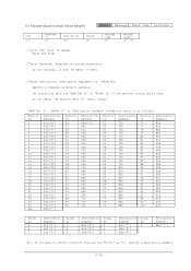
... 6Fh 70h 71h 72h Monitor ID 51 52 53 54 55 56 57 58 59 60 61 62 63 64 65 66 67 68 69 70 71 72 73 74 75 Destination Address 73h 74h 75h 76h 77h 78h 79h 7Ah 7Bh 7Ch 7Dh 7Eh 7Fh 80h 81h 82h 83h 84h...
... 6Fh 70h 71h 72h Monitor ID 51 52 53 54 55 56 57 58 59 60 61 62 63 64 65 66 67 68 69 70 71 72 73 74 75 Destination Address 73h 74h 75h 76h 77h 78h 79h 7Ah 7Bh 7Ch 7Dh 7Eh 7Fh 80h 81h 82h 83h 84h...

External Control Codes
Page 64
...):C0: Option board abnormality (64/72) Delimiter CR (0Dh): End of packet 2) The monitor replies a result of self-tests '0'-'0'(30h, 30h):00: Normal '7'-'0'(37h, 30h):70: Standby-power +3.3V abnormality '7'-'1'(37h, 31h):71: Standby-power +5V abnormality '7'-'2'(37h, 32h):72: Panel-power +12V abnormality '7'-'8'(37h, 38h):78: Inverter power/Option slot2...
...):C0: Option board abnormality (64/72) Delimiter CR (0Dh): End of packet 2) The monitor replies a result of self-tests '0'-'0'(30h, 30h):00: Normal '7'-'0'(37h, 30h):70: Standby-power +3.3V abnormality '7'-'1'(37h, 31h):71: Standby-power +5V abnormality '7'-'2'(37h, 32h):72: Panel-power +12V abnormality '7'-'8'(37h, 38h):78: Inverter power/Option slot2...

External Control Codes
Page 70
... the monitor to the controller. Header SOH-'0'-'0'-Monitor ID-'B'-'1'-'2' Message STX-'C'-'3'-'2'-'C'-MajorCH-MinorCH-ETX Check code Delimiter BCC CR Header SOH (01h): Start of packet (70/72)
... the monitor to the controller. Header SOH-'0'-'0'-Monitor ID-'B'-'1'-'2' Message STX-'C'-'3'-'2'-'C'-MajorCH-MinorCH-ETX Check code Delimiter BCC CR Header SOH (01h): Start of packet (70/72)
Specification Brochure
Page 2
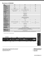
...Integrated (10W x 2) 150W 0.9/0.9, 0.9/0.9 in. / 23.0/23.0, 23.0/23.0 mm 62.5 x 36.2 x 3.4 in OPS slot for E705/E805/E905 MODEL LCD MODULE Panel Technology Viewable Image Size Native Resolution Brightness (Typical/Max) Contrast Ratio (Typical) Viewing Angle Aspect Ratio Active ...stand) VESA Hole Configuration ENVIRONMENTAL CONDITIONS Operating Temperature Operating Humidity Operating Altitude LIMITED WARRANTY ADDITIONAL FEATURES SHIPS WITH OPTIONAL ACCESSORIES Single Board Computers Other E705 UV2A 70" 360/450 cd/m2 4000:1 176° Vert. / 176 Hor.(88U/88D/88L/88R) @CR>10 60.6 x 34.1in....
...Integrated (10W x 2) 150W 0.9/0.9, 0.9/0.9 in. / 23.0/23.0, 23.0/23.0 mm 62.5 x 36.2 x 3.4 in OPS slot for E705/E805/E905 MODEL LCD MODULE Panel Technology Viewable Image Size Native Resolution Brightness (Typical/Max) Contrast Ratio (Typical) Viewing Angle Aspect Ratio Active ...stand) VESA Hole Configuration ENVIRONMENTAL CONDITIONS Operating Temperature Operating Humidity Operating Altitude LIMITED WARRANTY ADDITIONAL FEATURES SHIPS WITH OPTIONAL ACCESSORIES Single Board Computers Other E705 UV2A 70" 360/450 cd/m2 4000:1 176° Vert. / 176 Hor.(88U/88D/88L/88R) @CR>10 60.6 x 34.1in....

User's Manual
Page 5
... monitor. • Do not place any heavy objects on the power cord. The monitor should be grounded (earthed) in accordance with ANSI/NFPA 70, the National Electrical Code (NEC), in particular Section 820.93, Grounding of Outer Conductive Shield of a Coaxial Cable. • The screen of any kind into the cabinet slots...
... monitor. • Do not place any heavy objects on the power cord. The monitor should be grounded (earthed) in accordance with ANSI/NFPA 70, the National Electrical Code (NEC), in particular Section 820.93, Grounding of Outer Conductive Shield of a Coaxial Cable. • The screen of any kind into the cabinet slots...

User's Manual
Page 21
... OSD (On-Screen-Display) Controls NOTE: Some functions may not be adjusted. Input source Main Menu Icons Main Menu Item Sub Menu PICTURE MODE Select 70 50 50 50 50 50 THANK YOU FOR SAVING THE ENVIRONMENT.
... OSD (On-Screen-Display) Controls NOTE: Some functions may not be adjusted. Input source Main Menu Icons Main Menu Item Sub Menu PICTURE MODE Select 70 50 50 50 50 50 THANK YOU FOR SAVING THE ENVIRONMENT.

User's Manual
Page 22
to adjust. 50*2 NOTE: When sRGB is selected in picture mode, this function cannot be changed. to adjust. 70 NOTE: When MODE1 or MODE2 is selected in ROOM LIGHT SENSING, this function cannot be changed . GAMMA CORRECTION NATIVE Select a display gamma ...: When sRGB is selected in INPUT CHANGE and displayed, this function cannot be changed . To adjust the R/G/B levels, CUSTOM must be loaded using NEC optional software. NOTE: When sRGB is selected in INPUT CHANGE and displayed, this function cannot be changed . MOVIE SETTINGS NOTE: When INPUT2 of SUPER...
to adjust. 50*2 NOTE: When sRGB is selected in picture mode, this function cannot be changed. to adjust. 70 NOTE: When MODE1 or MODE2 is selected in ROOM LIGHT SENSING, this function cannot be changed . GAMMA CORRECTION NATIVE Select a display gamma ...: When sRGB is selected in INPUT CHANGE and displayed, this function cannot be changed . To adjust the R/G/B levels, CUSTOM must be loaded using NEC optional software. NOTE: When sRGB is selected in INPUT CHANGE and displayed, this function cannot be changed . MOVIE SETTINGS NOTE: When INPUT2 of SUPER...

User's Manual
Page 47
E705 Product Specifications LCD Module 70"/1765.6 mm diagonal Resolution: 1920 x 1080 Color: Over 16 million colors (depending on Green Video: 0.3 Vp-p Neg. English-45 HDMI/ HDMI2 HDMI Connector Y/Pb/Pr*2 ...
E705 Product Specifications LCD Module 70"/1765.6 mm diagonal Resolution: 1920 x 1080 Color: Over 16 million colors (depending on Green Video: 0.3 Vp-p Neg. English-45 HDMI/ HDMI2 HDMI Connector Y/Pb/Pr*2 ...

Installation Guide
Page 1
E705 Installation Guide 70" LCD Display NEC Display Solutions of Optional Wall Mount (WMK-3257) Input Terminals Control Codes Browser Control Page 1 Page 1 Page 2 Page 3-4 Page 5 Page 6 Page 7-8 Page 9 Page 10 Page ... the installation must be displayed on the 16:9 screen in either normal aspect ratio with any local building codes. MAXIMUM TILT ANGLE www.necdisplay.com E705 Page 1 of 11
E705 Installation Guide 70" LCD Display NEC Display Solutions of Optional Wall Mount (WMK-3257) Input Terminals Control Codes Browser Control Page 1 Page 1 Page 2 Page 3-4 Page 5 Page 6 Page 7-8 Page 9 Page 10 Page ... the installation must be displayed on the 16:9 screen in either normal aspect ratio with any local building codes. MAXIMUM TILT ANGLE www.necdisplay.com E705 Page 1 of 11

Installation Guide
Page 2
Rev 1.0 Ventilation Recommendations: Dimensions below are minimum recommended for design review and recommendations. NOTE: The ventilation space should not be incorporated into the design. E705 Installation Guide 70" LCD Display NEC Display Solutions of 11 www.necdisplay.com E705 Page 2 of America, Inc. If for some reason the opening needs to be covered, other means of ventilation will need to be covered or closed off at the front of the opening. Contact NEC for proper ventilation when the unit is in a recessed area.
Rev 1.0 Ventilation Recommendations: Dimensions below are minimum recommended for design review and recommendations. NOTE: The ventilation space should not be incorporated into the design. E705 Installation Guide 70" LCD Display NEC Display Solutions of 11 www.necdisplay.com E705 Page 2 of America, Inc. If for some reason the opening needs to be covered, other means of ventilation will need to be covered or closed off at the front of the opening. Contact NEC for proper ventilation when the unit is in a recessed area.

Installation Guide
Page 5
E705 Installation Guide 70" LCD Display Display Dimensions (with ST-801 stand): NEC Display Solutions of 11 Rev 1.0 www.necdisplay.com E705 Page 5 of America, Inc.
E705 Installation Guide 70" LCD Display Display Dimensions (with ST-801 stand): NEC Display Solutions of 11 Rev 1.0 www.necdisplay.com E705 Page 5 of America, Inc.

Installation Guide
Page 6
Rev 1.0 www.necdisplay.com E705 Page 6 of America, Inc. E705 Installation Guide 70" LCD Display Optional Table Top Stand Dimensions (ST-801): NEC Display Solutions of 11
Rev 1.0 www.necdisplay.com E705 Page 6 of America, Inc. E705 Installation Guide 70" LCD Display Optional Table Top Stand Dimensions (ST-801): NEC Display Solutions of 11

Installation Guide
Page 7
E705 Installation Guide 70" LCD Display NEC Display Solutions of 11 Rev 1.0 Dimensions of Optional Front-Firing Speaker (SP-TF1) www.necdisplay.com E705 Page 7 of America, Inc.
E705 Installation Guide 70" LCD Display NEC Display Solutions of 11 Rev 1.0 Dimensions of Optional Front-Firing Speaker (SP-TF1) www.necdisplay.com E705 Page 7 of America, Inc.

Installation Guide
Page 8
Rev 1.0 Optional Side-Firing Speaker Dimensions including holder (SP-RM1): www.necdisplay.com E705 Page 8 of America, Inc. E705 Installation Guide 70" LCD Display NEC Display Solutions of 11
Rev 1.0 Optional Side-Firing Speaker Dimensions including holder (SP-RM1): www.necdisplay.com E705 Page 8 of America, Inc. E705 Installation Guide 70" LCD Display NEC Display Solutions of 11

Installation Guide
Page 9
E705 Installation Guide 70" LCD Display NEC Display Solutions of 11 Rev 1.0 Dimensions of Optional Wall Mount Kit (WMK-3257): www.necdisplay.com E705 Page 9 of America, Inc.
E705 Installation Guide 70" LCD Display NEC Display Solutions of 11 Rev 1.0 Dimensions of Optional Wall Mount Kit (WMK-3257): www.necdisplay.com E705 Page 9 of America, Inc.

Installation Guide
Page 10
Rev 1.0 NOTE: Contact your NEC rep for codes not listed. The only connections required are not required. These connections are pins 2 (TxD), 3 (RxD) and 5 (GND). www.necdisplay.com E705 Page 10 of the cable to Send" together on both ends of 11 Cable Connection: Communication Protocol: Interface: Communication System: Baud...Used NOTE: If so desired, jumper "Request to send" and "Clear to simplify cable connection. NOTE: Use a cross/reverse/null modem cable. E705 Installation Guide 70" LCD Display Input Panels: Bottom: Control Codes: NEC Display Solutions of America, Inc.
Rev 1.0 NOTE: Contact your NEC rep for codes not listed. The only connections required are not required. These connections are pins 2 (TxD), 3 (RxD) and 5 (GND). www.necdisplay.com E705 Page 10 of the cable to Send" together on both ends of 11 Cable Connection: Communication Protocol: Interface: Communication System: Baud...Used NOTE: If so desired, jumper "Request to send" and "Clear to simplify cable connection. NOTE: Use a cross/reverse/null modem cable. E705 Installation Guide 70" LCD Display Input Panels: Bottom: Control Codes: NEC Display Solutions of America, Inc.

Installation Guide
Page 11
In order to accomplish this, type: http:// Rev 1.0 Browser Control Information and control can also be available through the HTTP browser control menu. E705 Installation Guide 70" LCD Display NEC Display Solutions of America, Inc.
In order to accomplish this, type: http:// Rev 1.0 Browser Control Information and control can also be available through the HTTP browser control menu. E705 Installation Guide 70" LCD Display NEC Display Solutions of America, Inc.
