Reference Guide
Page 5
... Code 39 Full ASCII, PDF417, GS1 Databar 14/Limited/ Expanded. DS6708-DL chapter. -Update Motorola Web sites. -Change: - Add custom defaults options; add ISBT ...concatenation parameters; change Dutch Postal references to Netherlands KIX Code, 4State Postal to USPS 4CB/One Code/Intelligent Mail, and Post US4 to GS1-128. Add DS6708 with base model, add cable... update operating temperature and drop specifications, remove sealing specification, correct Symbol PTC Terminal bar code, add new UPC/EAN supplemental options, Bookland...
... Code 39 Full ASCII, PDF417, GS1 Databar 14/Limited/ Expanded. DS6708-DL chapter. -Update Motorola Web sites. -Change: - Add custom defaults options; add ISBT ...concatenation parameters; change Dutch Postal references to Netherlands KIX Code, 4State Postal to USPS 4CB/One Code/Intelligent Mail, and Post US4 to GS1-128. Add DS6708 with base model, add cable... update operating temperature and drop specifications, remove sealing specification, correct Symbol PTC Terminal bar code, add new UPC/EAN supplemental options, Bookland...
Reference Guide
Page 17
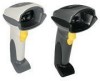
... includes all operating features of the digital scanner, beeper and LED definitions, and how to use the digital scanner in this guide are as follows: • Chapter 1, Getting Started provides a product overview, unpacking instructions, and cable connection information. • Chapter 2, Scanning describes parts of the Symbol DS6708 Standard Range digital scanner. NOTE The Symbol DS6708 premier digital decoder does not support imaging.
... includes all operating features of the digital scanner, beeper and LED definitions, and how to use the digital scanner in this guide are as follows: • Chapter 1, Getting Started provides a product overview, unpacking instructions, and cable connection information. • Chapter 2, Scanning describes parts of the Symbol DS6708 Standard Range digital scanner. NOTE The Symbol DS6708 premier digital decoder does not support imaging.
Reference Guide
Page 22
...for contact information. The digital scanner autodetects the host. • Configuration via 123Scan. If the digital scanner was damaged in transit, contact Motorola Enterprise Mobility Support. KEEP THE PACKING. Unpacking Remove the digital scanner from its packing and ...Brazilian, and Japanese. • Scanner Emulation connection to a host. 1 - 2 Symbol DS6708 Digital Scanner Product Reference Guide Supported Interfaces The DS 6708 digital scanner supports: • USB connection to the HID keyboard interface type. The digital scanner autodetects a USB host and defaults...
...for contact information. The digital scanner autodetects the host. • Configuration via 123Scan. If the digital scanner was damaged in transit, contact Motorola Enterprise Mobility Support. KEEP THE PACKING. Unpacking Remove the digital scanner from its packing and ...Brazilian, and Japanese. • Scanner Emulation connection to a host. 1 - 2 Symbol DS6708 Digital Scanner Product Reference Guide Supported Interfaces The DS 6708 digital scanner supports: • USB connection to the HID keyboard interface type. The digital scanner autodetects a USB host and defaults...

Reference Guide
Page 23
... vary from those illustrated, but the steps to the host (see Figure 1-3). 2. Gently tug the cable to connect a new cable. Using the tip of the interface cable to connect the digital scanner are examples only. Follow the steps for information on the bottom of the scanner handle (see the specific host chapter for Installing the Interface...
... vary from those illustrated, but the steps to the host (see Figure 1-3). 2. Gently tug the cable to connect a new cable. Using the tip of the interface cable to connect the digital scanner are examples only. Follow the steps for information on the bottom of the scanner handle (see the specific host chapter for Installing the Interface...
Reference Guide
Page 24
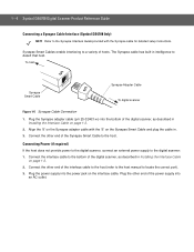
... power supply into an AC outlet. Connect the other end of the interface cable to the host (refer to the host manual to locate the correct port). 3. Connect the other end of hosts. 1 - 4 Symbol DS6708 Digital Scanner Product Reference Guide Connecting a Synapse Cable Interface (Symbol DS6708 0nly) NOTE Refer to the Synapse Interface Guide provided with the 'S' on...
... power supply into an AC outlet. Connect the other end of the interface cable to the host (refer to the host manual to locate the correct port). 3. Connect the other end of hosts. 1 - 4 Symbol DS6708 Digital Scanner Product Reference Guide Connecting a Synapse Cable Interface (Symbol DS6708 0nly) NOTE Refer to the Synapse Interface Guide provided with the 'S' on...

Reference Guide
Page 25
... turn the angle adjustment knobs right to tighten. Gently tug the cable to connect the digital scanner are examples only. Carefully slide out the cable. 5. NOTE Ensure the cable is full access to loosen the scanner in each host chapter are the same. Move the scanner to preferred angle and turn the angle adjustment knobs right to...
... turn the angle adjustment knobs right to tighten. Gently tug the cable to connect the digital scanner are examples only. Carefully slide out the cable. 5. NOTE Ensure the cable is full access to loosen the scanner in each host chapter are the same. Move the scanner to preferred angle and turn the angle adjustment knobs right to...

Reference Guide
Page 40
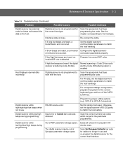
... read that pattern, but does not decode the the correct bar code type. Connect the correct host interface cable. The symbol is defaced. The USB bus may put the digital scanner in charge of bar code. 3 - 2 Symbol DS6708 Digital Scanner Product Reference Guide Troubleshooting Table 3-1 Troubleshooting Problem Possible Causes Possible Solutions The aiming pattern does not appear when...
... read that pattern, but does not decode the the correct bar code type. Connect the correct host interface cable. The symbol is defaced. The USB bus may put the digital scanner in charge of bar code. 3 - 2 Symbol DS6708 Digital Scanner Product Reference Guide Troubleshooting Table 3-1 Troubleshooting Problem Possible Causes Possible Solutions The aiming pattern does not appear when...
Reference Guide
Page 41
... bar code, but does not transmit the data to match the host's setting. Re-connect the cable. programming bar code. If 4 long low beeps are heard, a conversion Configure the digital scanner's or format error occurred. Digital scanner is not programmed for the parameter programmed. and the Code 39 Buffering option is buffering Code 39 data...
... bar code, but does not transmit the data to match the host's setting. Re-connect the cable. programming bar code. If 4 long low beeps are heard, a conversion Configure the digital scanner's or format error occurred. Digital scanner is not programmed for the parameter programmed. and the Code 39 Buffering option is buffering Code 39 data...

Reference Guide
Page 44
..., and multiple 6 ft. (1.8 m) drops to 95%, non-condensing Drop Specifications (For Scanner Only; 3 - 6 Symbol DS6708 Digital Scanner Product Reference Guide Table 3-2 Technical Specifications (Continued) Item Description Typical Working Distance 5 mil ...(Code 39): 10 mil (I 2 of the above plus many non-standard interfaces. IBM 468x/469x; and, Synapse Connectivity allows for applications that do not supply power over the host cable...
..., and multiple 6 ft. (1.8 m) drops to 95%, non-condensing Drop Specifications (For Scanner Only; 3 - 6 Symbol DS6708 Digital Scanner Product Reference Guide Table 3-2 Technical Specifications (Continued) Item Description Typical Working Distance 5 mil ...(Code 39): 10 mil (I 2 of the above plus many non-standard interfaces. IBM 468x/469x; and, Synapse Connectivity allows for applications that do not supply power over the host cable...
Reference Guide
Page 45
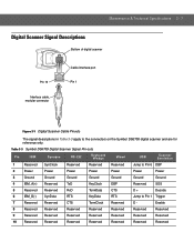
Table 3-3 Symbol DS6708 Digital Scanner Signal Pin-outs Pin IBM Synapse RS-232 Keyboard Wedge Wand USB Scanner Emulation 1 Reserved SynClock Reserved Reserved Reserved Jump to Pin 6 DBP 2 Power ... RTS KeyData RTS Jump to the connectors on the Symbol DS6708 digital scanner and are for reference only. Maintenance & Technical Specifications 3 - 7 Digital Scanner Signal Descriptions Bottom of digital scanner Pin 10 Interface cable modular connector Cable interface port Pin 1 Figure 3-1 Digital Scanner Cable Pinouts The signal descriptions in Table 3-3 apply to Pin...
Table 3-3 Symbol DS6708 Digital Scanner Signal Pin-outs Pin IBM Synapse RS-232 Keyboard Wedge Wand USB Scanner Emulation 1 Reserved SynClock Reserved Reserved Reserved Jump to Pin 6 DBP 2 Power ... RTS KeyData RTS Jump to the connectors on the Symbol DS6708 digital scanner and are for reference only. Maintenance & Technical Specifications 3 - 7 Digital Scanner Signal Descriptions Bottom of digital scanner Pin 10 Interface cable modular connector Cable interface port Pin 1 Figure 3-1 Digital Scanner Cable Pinouts The signal descriptions in Table 3-3 apply to Pin...

Reference Guide
Page 47
.... This is only necessary upon the first power-up beeps sound. If not using a USB cable or Synapse cable, select a host type (see the bar code clearly, and bars and/or spaces are preserved even when the digital scanner is not necessary. To set the document magnification to a level where you can program the...
.... This is only necessary upon the first power-up beeps sound. If not using a USB cable or Synapse cable, select a host type (see the bar code clearly, and bars and/or spaces are preserved even when the digital scanner is not necessary. To set the document magnification to a level where you can program the...

Reference Guide
Page 67
... a live host via a Synapse, use the Auxiliary Synapse Port connection. User Preferences & Miscellaneous Digital Scanner Options 4 - 21 Synapse Interface Parameter # F0h, ACh The auto-detection of a Synapse cable varies in duration depending on -board wedge host is enabled. *Standard Synapse Connection (01h) "...Connection (0Ah) Auxiliary Synapse Port Connection (32h) In all other cases, when using a Synapse cable, use the "Plug and Play" setting. To disconnect and reconnect the digital scanner from the default if an on the type of Synapse connection. Do not change this setting ...
... a live host via a Synapse, use the Auxiliary Synapse Port connection. User Preferences & Miscellaneous Digital Scanner Options 4 - 21 Synapse Interface Parameter # F0h, ACh The auto-detection of a Synapse cable varies in duration depending on -board wedge host is enabled. *Standard Synapse Connection (01h) "...Connection (0Ah) Auxiliary Synapse Port Connection (32h) In all other cases, when using a Synapse cable, use the "Plug and Play" setting. To disconnect and reconnect the digital scanner from the default if an on the type of Synapse connection. Do not change this setting ...

Reference Guide
Page 69
...return all features to perform various functions, or activate different features. To set the document magnification to a level where you can program the digital scanner to default values, scan the Set Default Parameter on page 5-2 (also see Appendix A, Standard Default Parameters for all host device and miscellaneous...5 Decoding Preferences Introduction You can see the bar code clearly, and bars and/or spaces are not merging. If not using a USB cable, select a host type (see each host chapter for selecting these features. This is only necessary upon the first power-up beeps sound....
...return all features to perform various functions, or activate different features. To set the document magnification to a level where you can program the digital scanner to default values, scan the Set Default Parameter on page 5-2 (also see Appendix A, Standard Default Parameters for all host device and miscellaneous...5 Decoding Preferences Introduction You can see the bar code clearly, and bars and/or spaces are not merging. If not using a USB cable, select a host type (see each host chapter for selecting these features. This is only necessary upon the first power-up beeps sound....

Reference Guide
Page 76
... 4690 OS. The following operating systems support the digital scanner through USB: • Windows® 98, 2000, ME, XP • MacOS 8.5 - 6 - 2 Symbol DS6708 Digital Scanner Product Reference Guide Connecting a USB Interface USB Series A Connector Interface Cable Figure 6-1 USB Connection USB Series A Connector Interface Cable Figure 6-2 USB Connection for Scanner with Base The digital scanner connects with USB-capable hosts including: •...
... 4690 OS. The following operating systems support the digital scanner through USB: • Windows® 98, 2000, ME, XP • MacOS 8.5 - 6 - 2 Symbol DS6708 Digital Scanner Product Reference Guide Connecting a USB Interface USB Series A Connector Interface Cable Figure 6-1 USB Connection USB Series A Connector Interface Cable Figure 6-2 USB Connection for Scanner with Base The digital scanner connects with USB-capable hosts including: •...

Reference Guide
Page 77
... click Finished on page 6-5. USB Interface 6 - 3 The digital scanner also interfaces with Leading Zero Disable USB FN1 Substitution Disable Page Number 6-5 6-6 6-8 6-8 6-9 6-9 6-10 6-10 The digital scanner powers up the digital scanner: NOTE Interface cables vary depending on page 3-2. The connectors may be different than those... set up during this chapter. The connectors illustrated in an available port of the USB interface cable to the cable interface port on the digital scanner (see Troubleshooting on configuration. Plug the series A connector in the USB host or hub, or...
... click Finished on page 6-5. USB Interface 6 - 3 The digital scanner also interfaces with Leading Zero Disable USB FN1 Substitution Disable Page Number 6-5 6-6 6-8 6-8 6-9 6-9 6-10 6-10 The digital scanner powers up the digital scanner: NOTE Interface cables vary depending on page 3-2. The connectors may be different than those... set up during this chapter. The connectors illustrated in an available port of the USB interface cable to the cable interface port on the digital scanner (see Troubleshooting on configuration. Plug the series A connector in the USB host or hub, or...

Reference Guide
Page 99
...set up the digital scanner with most system architectures. For system architectures requiring RS-232C signal levels, Motorola offers different cables providing TTL-to point-of-sale devices, host computers, or other devices with an available RS-232 port (e.g., com port). NOTE The digital scanner uses TTL RS-...computer monitors allow scanning the bar codes directly on the screen. Use the RS-232 interface to connect the digital scanner to -RS-232C conversion. Contact Motorola Enterprise Mobility Support for the host device to set the document magnification to a level where you can see...
...set up the digital scanner with most system architectures. For system architectures requiring RS-232C signal levels, Motorola offers different cables providing TTL-to point-of-sale devices, host computers, or other devices with an available RS-232 port (e.g., com port). NOTE The digital scanner uses TTL RS-...computer monitors allow scanning the bar codes directly on the screen. Use the RS-232 interface to connect the digital scanner to -RS-232C conversion. Contact Motorola Enterprise Mobility Support for the host device to set the document magnification to a level where you can see...

Reference Guide
Page 100
...host computer. Serial Port Connector to Host Interface Cable Power Supply Cable Figure 7-1 RS-232 Direct Connection Serial Port Connector to the cable interface port on the digital scanner (see Installing the Interface Cable on configuration. The connectors illustrated in Figure 7-1...the modular connector of the RS-232 interface cable to Host Base Interface Cable Power Supply Cable Figure 7-2 RS-232 Direct Connection for Scanner with Base NOTE Interface cables vary depending on page 1-3). 7 - 2 Symbol DS6708 Digital Scanner Product Reference Guide Connecting an RS-232 Interface...
...host computer. Serial Port Connector to Host Interface Cable Power Supply Cable Figure 7-1 RS-232 Direct Connection Serial Port Connector to the cable interface port on the digital scanner (see Installing the Interface Cable on configuration. The connectors illustrated in Figure 7-1...the modular connector of the RS-232 interface cable to Host Base Interface Cable Power Supply Cable Figure 7-2 RS-232 Direct Connection for Scanner with Base NOTE Interface cables vary depending on page 1-3). 7 - 2 Symbol DS6708 Digital Scanner Product Reference Guide Connecting an RS-232 Interface...

Reference Guide
Page 101
To modify any other end of the RS-232 interface cable to the serial connector end of the RS-232 interface cable. Plug the power supply into an appropriate outlet. 4. Select the RS-232 host type by scanning the appropriate bar code from RS-232 Host Types on the host. 3. Connect the power supply to the serial port on page 7-7. 5. RS-232 Interface 7 - 3 2. Connect the other parameter options, scan the appropriate bar codes in this chapter.
To modify any other end of the RS-232 interface cable to the serial connector end of the RS-232 interface cable. Plug the power supply into an appropriate outlet. 4. Select the RS-232 host type by scanning the appropriate bar code from RS-232 Host Types on the host. 3. Connect the power supply to the serial port on page 7-7. 5. RS-232 Interface 7 - 3 2. Connect the other parameter options, scan the appropriate bar codes in this chapter.

Reference Guide
Page 124
... configuration. Host Port Connector Figure 8-1 IBM Direct Connection Interface Cable Interface Cable Host Port Connector Figure 8-2 IBM Direct Connection for Scanner with Base NOTE Interface cables vary depending on page 1-3. 2. 8 - 2 Symbol DS6708 Digital Scanner Product Reference Guide Connecting to an IBM 468X/469X Host Connect the digital scanner directly to the appropriate port on the host (typically Port 9). 3. The IBM...
... configuration. Host Port Connector Figure 8-1 IBM Direct Connection Interface Cable Interface Cable Host Port Connector Figure 8-2 IBM Direct Connection for Scanner with Base NOTE Interface cables vary depending on page 1-3. 2. 8 - 2 Symbol DS6708 Digital Scanner Product Reference Guide Connecting to an IBM 468X/469X Host Connect the digital scanner directly to the appropriate port on the host (typically Port 9). 3. The IBM...

Reference Guide
Page 130
... the same. 1. Connect the other end of the Wand Emulation interface cable to cable interface port on the digital scanner (see Installing the Interface Cable on the mobile computer or controller. 9 - 2 Symbol DS6708 Digital Scanner Product Reference Guide Connecting Using Wand Emulation To perform Wand Emulation, connect the digital scanner to a mobile computer, or a controller which collects the wand data and...
... the same. 1. Connect the other end of the Wand Emulation interface cable to cable interface port on the digital scanner (see Installing the Interface Cable on the mobile computer or controller. 9 - 2 Symbol DS6708 Digital Scanner Product Reference Guide Connecting Using Wand Emulation To perform Wand Emulation, connect the digital scanner to a mobile computer, or a controller which collects the wand data and...
